QuestionQUESTION: Hi Howard,
I came to the same conclusion as you after I couldn't find the fault so a few days ago I ran a wire from a fuse behind the instrument panel that had a spare spade connection and ran it through the firewall to the coil. I think it was fuse #7 that is only live when the key is 'on' and it also operates the turn signals and wipers. I thought I may as well add a toggle switch hidden in the passenger area to create something of an anti theft device. I bought an after market ballast resistor of 0.8 ohms (only one the store had) because the original set up used a resistor of .9 to 1.0 ohms as per the manual and I still have the stock coil which is 12 volts. The manual had several tests for the coil, positive to ground should read 4 - 6 volts, when ignition is 'on', currently my coil is reading 7 volts. Coil negative to ground when ignition is 'on' is supposed to be less than 2 volts, my reading was 1.8V. I guess the voltage is brought down to keep the coil cooler and preserve it's life or that of the distributor primary circuit or the amplifier ? You said to run 12 volts to the coil but it looks like the original set up was to run 4 - 6 volts to the 12 volt coil. I don't have points ignition, I have the stock 'Opus' electronic with the timing rotor with the rods and the pickup module. I know it's common to lower the voltage to the coil with points ignition, to extend the life of the points but I guess it was also used with the Opus system ?
Thanks again,
Steve
ANSWER: Hi Steve,
Let me know if that works as I can't see how you can fire a 12v coil through a resistor. Some of the V-12 XJ-S cars used a dual coil, using only one of the secondaries. The second coil was called a slave coil. I don't have much data on the V-12 E-type and it has been too many years since I worked on one.
Do this, remove the wires from the coil and check the ohms across (+) to (-) and see if it is close to .8 to 1 ohm or is it up around 3+ ohms? Both these cars use a 6 pin ballast resistor.
If you measure 1.1 ohms or less, I believe that is the correct coil for the car.
The coil used on the XJ-12 cars is .8 to 1. ohm across the primary on the Opus/Lucas system.
The coil used on the XJ-S cars is .9 to 1.1 ohms.
On almost every car in the world, when a 6v coil is used they need a ballast resistor otherwise the 12v would overheat and fry the coil. They get away with running a straight 12v to that 6v coil in the start position because the starter draws so much current it drops the available voltage down so as not to fry the coil and as soon as the key is released to the "Run" position the power is cut off to the coil and a new power is routed through a resistor to drop the voltage so as not to over heat the coil.
As I remember the resistor was a large 6 pin flat resistor mounted either under the coil or next to it.
I have several diagrams of the Sedans and the "S" cars so if you have a diagram of your car post it so I can look at it and compare it to some of the ones I have.
Don't connect straight 12v to the coil unless the resistance is up around 3 ohms. If it is close to what I have for the sedans or the "S" you have to go through that resistor pack.
Let me know,
Howard
---------- FOLLOW-UP ----------
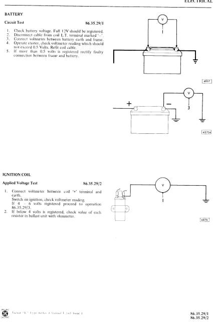 Coil test
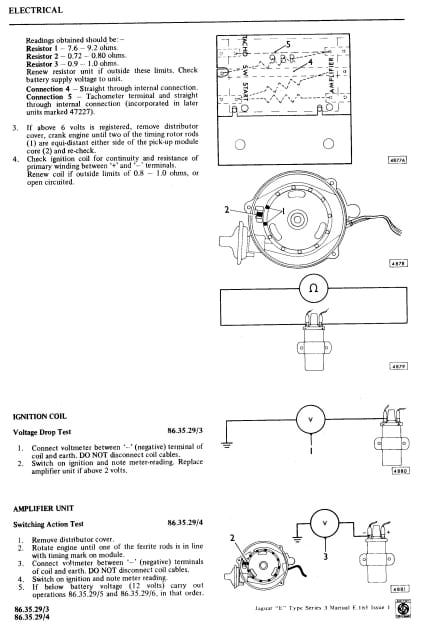 resistor test
QUESTION: Howard,
The resistance of the coil between + and - is 1.3 ohms. The manual says it should be between .8 and 1.0 ohms. Usually the specs give a reading at a specific temperature, it was about 44 degrees in my garage so it was cold, don't know if the resistance goes up or down with temperature... I sent you a overall drawing of the ignition system in a previous email, I've attached some more here. Let me know if you can read them. Yes I do have that flat, 6 pin resistor pack under the coil, the bottom left pin ('start') goes to the starter relay, the bottom right ('amplifier') goes to the coil positive. But there is only power from the relay when cranking, nothing when the key is at the 'on' position, hence the live wire I've attached to coil positive. Should I splice my new line into the line going to the 'start' terminal (bottom left) of the resistor pack ? That way I'd still be using the original resistor... I assume there is straight pass through from left to right of the resistor pack for each terminal ?
Thanks again,
Steve
ANSWER: I believe you have the wrong coil installed and no, on the straight across the resister pack as your "Resister Test" diagram shows. Just test the resistor as you show in your test.
You also need a diagram of the ignition system to get the power from the ignition switch correct too. And you need the correct coil. If you have an E-Type manual, it should list the correct coil. Then with the diagram you should be able to correct the wiring of the car too.
As we often found people along the way made changes that should not have been made. Make a picture of the whole ignition diagram or if it don't have that separatted, make one of the whole electrical system for me and I will try to make one out of it just for the ignition system for you.
Howard
---------- FOLLOW-UP ----------
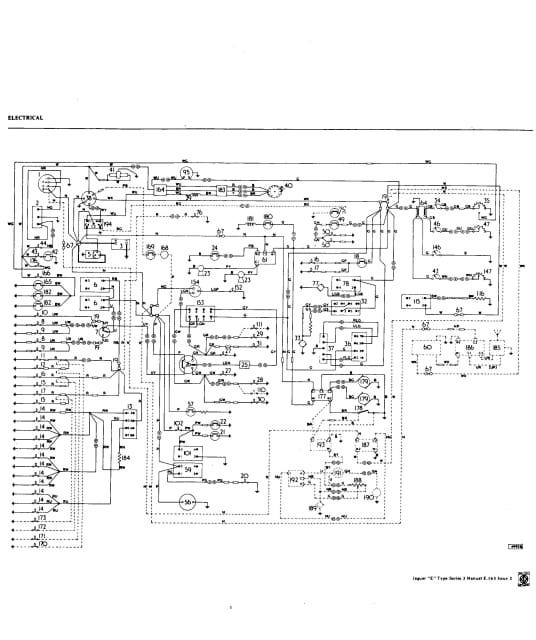 Electrical 1
 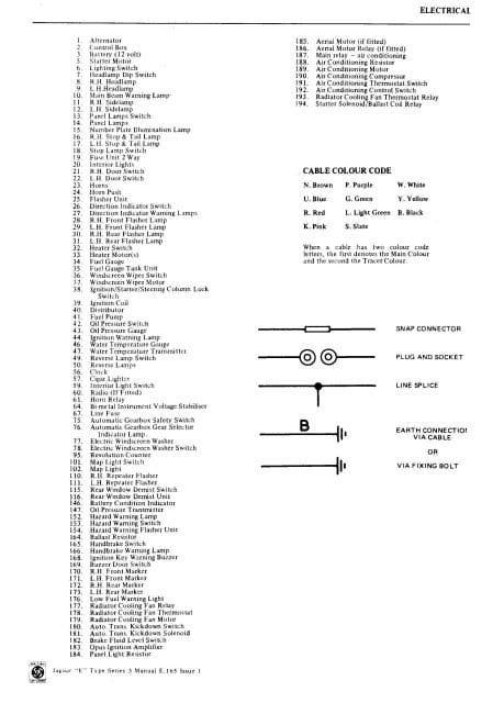 Electrical 2
QUESTION: Hi Howard,
According to the manual, the correct coil is 13C12 - and that's what's stamped on the bottom of my coil so it seems to be correct but maybe it's time it got replaced. I've attached the car's wiring diagram. I tested the resistor pack from left to right, but I don't understand what the zig zag lines mean in the resistor test drawing, if it means there are multiple connections inside... From the bottom left terminal (start) to bottom right I get 1.4 Ohms, if it's 'Resistor 3' as per the drawing, it should be .9 to 1.0. The middle ones were 0.6 ohms, when they should be .72 to .8. The top pair are not used in my car, instead there is a separate small black in line resistor for the tachometer. It's labelled Lucas RD953066 and is about 7 ohms which is close to what the drawing shows for Resistor 1. When I measured the unused top pair in the resistor pack (Tacho) it was 103 ohms, so that's probably why it wasn't used.
Thanks again for all your help !
Steve
AnswerI couldn't read the wiring diagram due to the low resolution of the picture. Could you take the picture again at a higher resolution so I can enlarge it. You can e-mail it to me at
fitzcharlesh@bellsouth.net
Do the index also.
Really surprised that you still have the Opus/Lucas system as we had so many failures we had to replace the units more then once while still in warranty.
I do remember that we did get a retro fix for all the V-12s from Lucas. I don't remember all the details except that with the dist cap off the pick-up looked like most pick-ups but the replacement from Lucas was a full circuit board that filled the distributor so when it was installed and someone took the cap off, it looked like the inside of a radio or TV set. That is the best that I can remember. I don't have any part numbers on any of them.
Howard