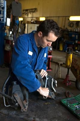
Harley-Davidson flywheel assemblies have undergone one major change in the last century. From 1909 until 1986, Harley crankshaft assemblies were actually constructed of numerous individual parts. Harley simplified this construction in 1987. One dives deep into the crankcase either because one has thrown a rod or otherwise blown one's engine apart or because one wants to balance the flywheels. Nothing else is worth it. Reaching the flywheel assembly requires the complete disassembly of the rest of the engine. Here is what you can do to a flywheel assembly on a post-1986 engine after you have taken everything else apart.
Hold the flywheel assembly so it does not tumble out of the left crankcase half. Rotate the bottom end assembly in an engine stand so the assembly is upright and the flywheel shafts are horizontal.
Carefully slide the flywheel assembly out of the left crankcase.
Install aluminum vise jaws and shop rags in the jaws of a bench vise. Clamp the flywheel support structure in the vise.
Insert the crankshaft end through the hole in the middle of the flywheel support structure.
Slide the structure's knurled locating pin down the slot in the structure to engage the crank pin hole. Hand tighten the locating pin.
Slide the structure's hold-down clamp down the slot to engage the inboard side of the right flywheel half. Hand tighten knurled nut at bottom to secure. Repeat step above to secure the hold-down clamp on the opposite side of the flywheel.
Position the wedge attachment on the inboard side of the thrust washer. Turn both hex nuts on the bottom of the wedge attachment an equal number of turns with an open end wrench to draw the wedge halves together.
Install two 6 1/2-inch-long, 3/8-inch bolts with flat washers through the channels in the bridge of a main shaft bearing inner race puller-installer. Thread both bolts into the wedge attachment an equal number of turns.
Apply graphite lubricant to the threads of the main shaft bearing inner race puller-installer forcing screw. Start the forcing screw into the bridge of the inner race puller-installer.
Place the cupped side of the hardened plug against the end of the sprocket shaft. Thread the forcing screw through the bridge until the screw makes firm contact with the hardened plug.
Heat the bearing inner race for 30 seconds with a heat gun. Turn the forcing screw with a breaker bar and hex socket until the thrust washer and bearing inner race move 1/8 inch.
Loosen the hex nuts on the long bolts in the wedge attachment with an open-end wrench. Turn each nut an equal number of times to separate the halves of the wedge attachment.
Turn the wedge attachment one half turn and retighten the hex nuts on the long bolts. Tighten each nut an equal number of turns to draw the wedge halves together.
Heat the bearing inner race for 30 seconds with a heat gun. Turn forcing screw with a breaker bar and hex socket until bearing inner race pulls free of socket.
Discard thrust washer and bearing inner race. Original post-1986 equipment flywheels are now completely disassembled.
Reassemble the flywheel assembly with a new thrust washer and new bearing inner race. Other parts may be cleaned and reused.