
Our '06 2WD F-150 has been a fun truck and we've done some mild suspension upgrades over the last year or so. But, we were ready to take the performance up a few more notches. We were looking to add a long-travel front suspension and immediately turned our attention to the guys at JD Fabrication in Escondido, California. Jesse Nelson and Dave Dinsmore have been building off-road hardware and vehicles for more than a decade. Along with doing full custom work, they offer a handful of long travel kits for 2WD and 4WD trucks.
We were after one of their '04-and-up 2WD F-150 kits that widen overall track width by 8 inches and offer 16 inches of usable wheel travel. Their kits have been proven in use for a number of years now. In fact, one of their F-150 kits was used during early prototype development of the Ford Raptor.
The kit comes quite complete with 4130 chromoly boxed lower A-arms, billet aluminum or steel boxed upper A-arms, custom lift spindles, heavy-duty tie rods, and shock mounts with an over-the-engine crossover tube. FK rod ends and uniballs, Crown Performance brake lines, and all other hardware are included, as well. The kit offers the option of running a coilover shock along with a bypass shock, and a hydraulic bumpstop. We opted to use Bilstein coilovers with Eibach springs, combined with Bilstein bumpstops.
The kit can be installed in about a weekend if you have the ability to do a little metal cutting and the welding needed for the shock mounts, bumpstop cans, and limit strap tabs. We had Nelson perform the installation in his shop and followed along as he pushed our F-150 to a much higher level of off-road performance.
 1. Here are the pieces included in the kit. It’s well thought out and complete, so you can get almost everything you’ll need, except shocks and bumpstops, in this one package.
 2. The conversion started at JD Fabrication with the truck on stands. All the stock A-arms, coilover shocks, steering rods, spindles, and related hardware were removed. The conversion retains the factory unit bearings, hubs, and brake components.
 3. This is one of the new shock mounts. The top of the factory mount is cut off and this piece extends the top end to accommodate mounting of both a coilover and bypass shock. It’s secured in place using the upper A-arm bolts and five bolts in the bottom that go through the stock shock mount.
 4. Nelson also adds four short welds to secure the new shock tower to the factory shock tower. JD has adopted this bolt/weld mounting method over fully welding the mounts. With this, you can grind off a few welds and unbolt the mount should you ever need access in this area. Their attention to the details in their kit is impressive.
 5. A bolt-in crossover tube sits just under the hood and ties the two shock towers together to provide better support and distribute the shock load across the frame.
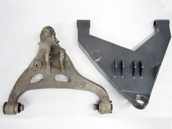
 6. The factory lower A-arms are cast aluminum. The JD arms are internally boxed and constructed from 4130 chromoly plate. The increase in the length of the new arm is evident here.
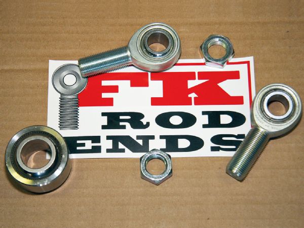
 7. FK uniballs and rod ends were used throughout. FK offers a wide range of spherical ball products. We were using their self-lubricating Teflon-lined components, which should offer long life. The lower arms use 1-inch uniballs and the upper arms and steering use 3/4-inch rod ends.
 8. The lower A-arm mount tabs on the frame are slotted at the factory to allow for suspension alignment adjustments. JD provides these plates that lock the position of the lower A-arm bolts. Caster and camber adjustments will be made by adjusting the rod ends on the upper A-arms, and alignment should only need to be set once for a given ride height.
 9. The billet upper arms are a CNC work of art.
 10. The parts install started with bolting the A-arms onto the frame. The lower arms use greased polyurethane bushings. Nelson suggests cleaning up the upper arm boltholes with a carbide burr to ensure the arm bolts can slide in and out freely. Your alignment guy will thank you for this little effort.
 11. The factory spindle shafts are reused. Nelson pressed them out of the stock spindles and transferred them to the JD chromoly lift spindles.
 12. Here are the major components assembled. The custom chromoly spindle bolts to a uniball pressed into the lower A-arm and mates to a second vertical uniball that bolts to the billet upper arm. The kit positions the front tires forward about 1 inch from stock for better fender clearance for larger tires.
 13. The factory steering rods were removed and stainless steering clevises installed in their place. The factory rack-and-pinion boots are reused and slipped on later.
 14. JD provides heavy-duty aluminum steering rods with rod ends to replace the thin factory rods. High misalignment spacers are used on the spindle rod end to accommodate the high travel angle.
 15. With the arms and spindle mounted, Nelson cycled the suspension to take some measurements and determine bumpstop placement for use with the Bilstein coilovers.
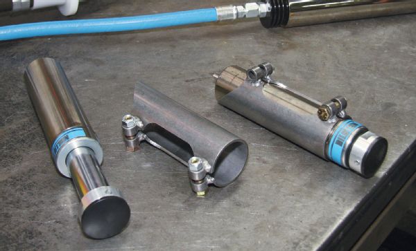 16. We sourced a set of 2-inch diameter, 3-inch travel Bilstein bumpstops and mount cans to halt our upward suspension travel. Each hydraulic bump contacts a pad on the lower A-arm.
 17. Nelson tack-welded the cans in place, then rechecked the suspension movement. Satisfied with the height and angle of the mount can, he reinforced them on the frame with some added plates.
 18. For shocks we opted to use Bilstein 9100 Series 60mm coilovers. Ten-inch travel shocks were used with their remote reservoir. These shocks are fully tunable and rebuildable.
 19. The coilover reservoirs were optioned with Bilstein’s anti-cavitation valve (ACV). The valve is a stationary piston designed to exponentially increase the internal pressure of the shock oil as the velocity of the shaft movement increases. This allows this shock to offer a comfortable ride over smaller bumps but still provide greater damping to reduce bottoming under harder use.
 20. Eibach springs were used on the coilovers using a combination of an 18-inch 700-pound coil and a 4-inch 500-pound coil. Eibach has a wide range of springs available, so if we decide to tweak the rate a bit they should be able to provide any spring we need.
 21. With the coils assembled on the coilover shock, the shock was bolted in place. The kit is designed to allow use of a coilover and bypass shock pair. We’re trying this build with the Bilstein 9100 coilovers with their added ACV alone.
 22. Crown Performance stainless braid brake lines were used. Longer lines are needed to accommodate the lift spindle and increased downward travel. We like the Crown lines because they mate to the factory steel lines and calipers perfectly, and they are fully DOT legal lines.
 23. One of the last steps to the suspension install was the addition of limit straps. With a floor jack under the lower A-arm to position the suspension just above the point of full shock extension, the limit strap tab was welded to the frame.
 24. Here’s just one of the little details that JD adds to some of their products. The limit strap tabs can use bolthole inserts with a centered or offset hole. Over time, as the limit strap stretches, a different insert can be installed to tighten up the droop limit again as needed.
 25. With Nelson putting the final pieces in place, it’s evident our F-150 will have a meaner stance and far more capable front suspension. Next steps will be adding some fiberglass fenders and bedsides, and then we address the rear suspension. Look to see our truck headed back into the dirt soon.


