Re-creating a vintage drag car, or building a new nostalgia-style build, is a fairly straightforward and affordable project. You can either do an absolutely period-correct build or a totally modern build wrapped in a vintage-style body and paintjob. For our altered tribute project, we’re leaning more toward period-correct than modern, but with some concessions.
For instance, the car we’re copying ran a three-speed manual trans; we’ll run an automatic—with a modern shifter. The original ran spindle mounts with rear brakes only, and probably had a hand brake. We’re running front discs and a dual reservoir master cylinder with a foot pedal. The original had no radiator or cooling system, save for what water was sealed inside the block; we’ll run a radiator under the decklid so that Southern summer heat won’t be as big a danger. And, of course, there’s the legal full ’cage over the driver’s compartment, in place of the single hoop and two down bars of the original.
For the most part, those will be our only concessions to modernity. One setup we’ve made a point of keeping period-correct is the steering gear. We’re not sure when Corvair steering boxes first showed up in race cars, but the aluminum boxes hit dealer showrooms in the fall of 1959. As delivered from the factory, the steering shaft is on the wrong end, but a little work with a drill press and a freeze plug corrects that by “reversing” the box so it has the proper orientation for hot rodders.
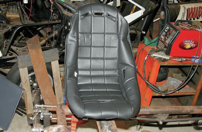 We began our steering box install by setting up the seat. Driver position will determine steering wheel position and column angle, which dictates steering box location. We’re not sure what the original car had for a seat, but a low-back bucket would be correct at least for the mid-to-late ’60s, and Summit carries them. We ordered an RCI seat and black seat cover. The cover will stay in the box until final assembly.
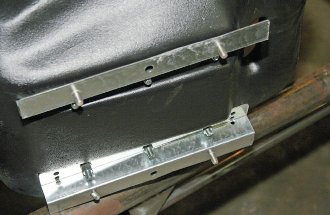 The seat comes with simple mounting brackets attached. We needed to fabricate something to bolt these to the car.
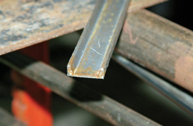 Nothing exotic: We used simple 1.5-inch-wide C-channel from the local industrial salvage yard.
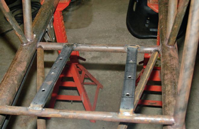 Here are the channels installed in the chassis. Rules require the seat mounts to be incorporated into the forward tube crossmember.
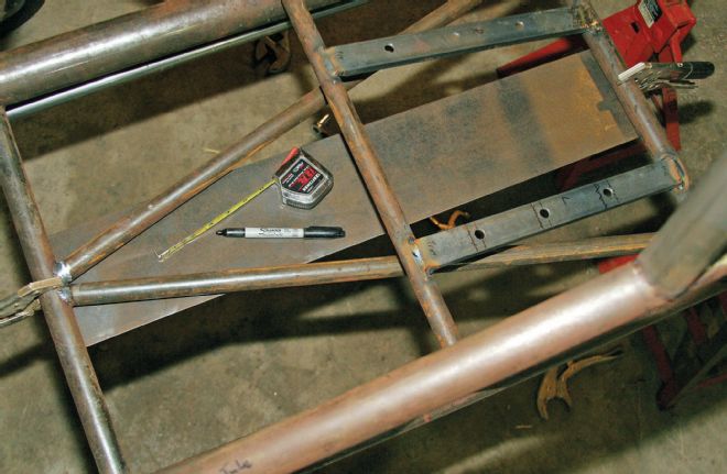 The rules also require the tube “wishbone” and forward crossmember in the floor for driver protection. We wanted a little more protection in case of driveshaft failure since our legs and other, more favored body parts are located right above the driveshaft. Faster classes require a fully enclosed driveshaft tube; we’ll have front and rear driveshaft loops. We made our Jimmy Plate out of 6-inch-wide, 1⁄8-inch-thick plate and welded it at the front and rear driver’s compartment crossmembers. This should be enough to keep us from springing a leak if the driveshaft grenades.
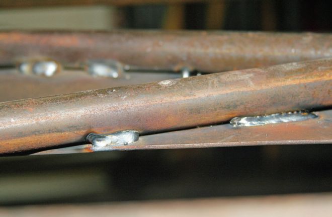 A lot of race cars end up having rattles and vibrations. Everywhere metal touches, it’ll vibrate if there’s any play or give. The Jimmy Plate is welded at the front and rear, and we added a few beads to the wishbone bars just to keep it from rattling against them while the car is idling.
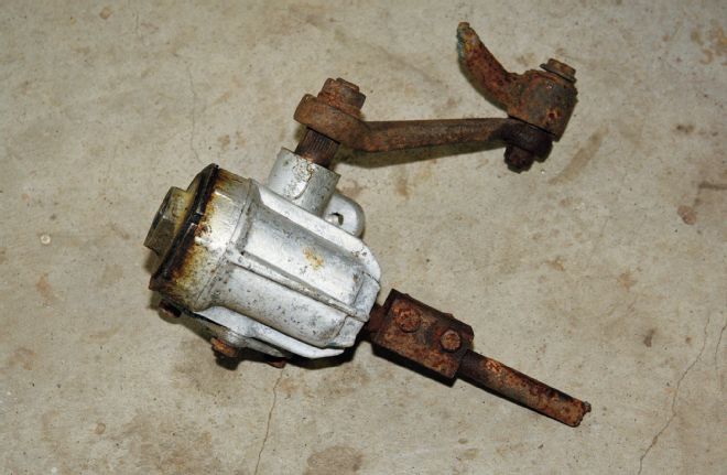 We had a reversed Corvair box in the shop already, but we needed a coupler. As if by Providence, the week after we came up with the plan, our swap meet yielded a complete box with the coupler and the last 8 inches of the factory steering column. For $70, we got the box and, more importantly, the pieces we need.
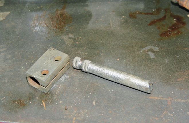 We soaked the coupler and the end of the factory steering shaft in vinegar overnight to derust it. We’ll slip the stub into a piece of tubing to form our new steering column.
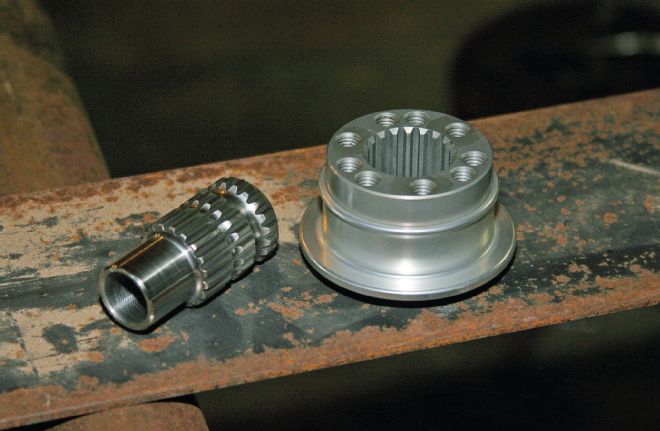
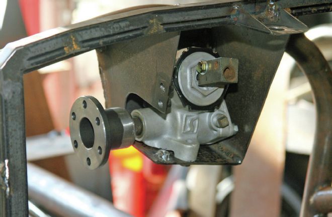
 This is the Corvair box center-steer conversion from Ron Pope Motorsports. It uses our box, a coupler for the pitman shaft, an extension, and then a pitman arm that runs perpendicular to the ground.
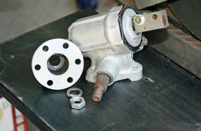 RPM’s coupler uses the splined end of the original pitman arm cut off and turned on a lathe, then welded inside the tube segment of the union. It then installs on the box’s pitman shaft as per original. We’ve found over the years that the threaded end of the pitman shaft is often damaged from corrosion, so use care when disassembling. Heat and a lot of penetrating oil help take an original box apart, and we limited the number of times we bolted the coupler to the box.
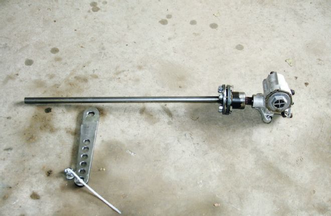
We have no idea what the original 78 car used for a steering box, but as the car was built in ’61, a Corvair box is era-correct. The next problem was converting it to a center-steer configuration. Ron Pope Motorsports supplied us with the whole front suspension, and it turns out the company already had a center-steer conversion kit for Corvair boxes.
We’re not sure when quick-disconnects made the scene, but given the confines of the full ’cage, the added clearance of a removable steering wheel is welcome. There are several styles of quick-disconnect, the most common, and least expensive, use a single pin that moves side to side, mounted below the shaft’s centerline. We went with the full 360-degree ring that you grab with your fingers and it releases. If the car is ever on its side or upside down, we don’t want to hunt for the pin. Then we had to decide between splined versus hex male/female union. We posed the question on a racing website, and a lot of racers said the hex mount will get sloppy over time and recommended the splined union.
For the shaft supports—both pitman and steering—“pillow block” bearings and Heim joints are commonly used. We have an industrial salvage place near us and came up with the pillow block and some lengths of steel we’d need. A trip to McMaster-Carr’s website yielded the Heim and a length of tubing for the steering column. If you’ve never used McMaster-Carr, it’s an industrial supplier that has everything you’d need to fabricate or repair anything.
 We needed to mount the box to the firewall hoop of the ’cage, but we also needed some kind of structure to support the steering column. We created another hoop out of 1-inch box tubing, and it will help support the box, the steering column, and will also mount the instrument panel. We made a couple of cuts along the length to bend the piece so it roughly followed the curvature of the cowl, then welded them closed.
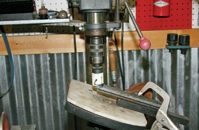 A drill press with a tilting table and a hole saw were used to match the angle of the cockpit’s tubing. We’ve never gotten around to buying one of those tubing notchers, and this is why.
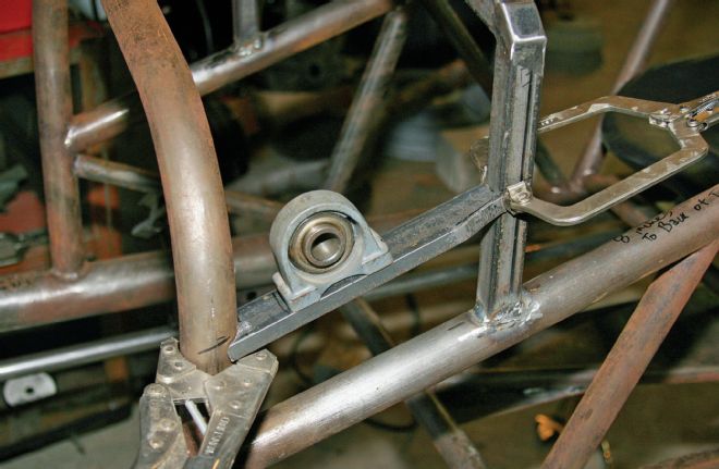 We needed something to hold the steering shaft, and it needs to be stout. All the forces working against each other in the steering linkage are going to be centered here, which will make the shaft want to flex if it isn’t rigidly supported. We used a pillow block bearing and a length of that 1.5-inch C-channel to mount it.
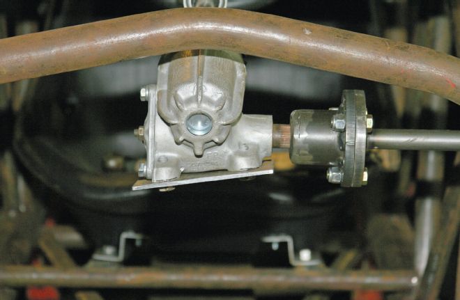
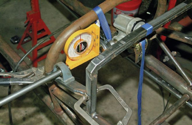 Mounting the steering box and shaft to a point in space, and making sure it’s all square and level to the chassis, takes some finagling. We hung the box with a ratchet strap, then located the pillow block support and mount so the shaft was level. At this point, the bearing’s mount isn’t welded to the ’cage yet.
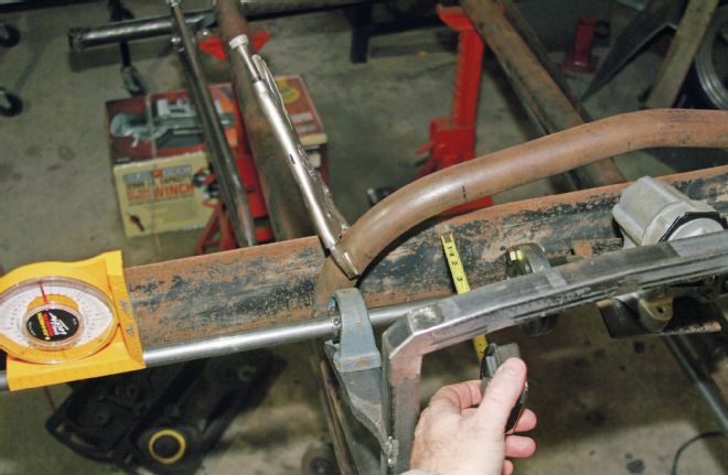 Once we had the shaft’s angle determined, we welded the bearing’s mount to the ’cage, then figured the rest based on it. We clamped a plate across the firewall hoop so we had a place to take a measurement so the shaft is square to the axle and crossmembers. As the shaft rotates through its range of motion, the pitman arm is hanging down from it. If the shaft isn’t square to the chassis on all planes, the pitman will not go through its range of motion squarely.
 With the box’s position determined, we created the steering column’s support mount. We used a piece of 1x3 box tubing and cut it down.
 The column is 3⁄4-inch OD, 5⁄8-inch ID tubing, supported by a 3⁄4-inch Heim joint. The tubing dimensions were determined by the steering wheel quick-disconnect and the Corvair steering shaft section, giving it a 1⁄16-inch wall. If we had a lathe, we’d have turned the end of the shaft down and gone with a little thicker wall. However, the mechanical advantage of the steering box internals means there isn’t a lot of force on the shaft when we’re turning the wheel, so we feel the thin wall will be OK. It’s also short, so there won’t be much flex along its length, and it’s supported in the middle. The angle of the steering column is determined by driver position: Basically, tilt it until it’s comfortable for you, then set it there.
 A Longacre Racing Products steering wheel quick-disconnect came from Summit. It has several sets of steering wheel mounting holes for different wheels and welds to the steering column shaft.
 With the steering box located and mounted at the pitman and steering shafts, we finally began building the box mount itself. There isn’t a single square angle anywhere on the mount. We began with the bottom plate to start fabricating the mount.
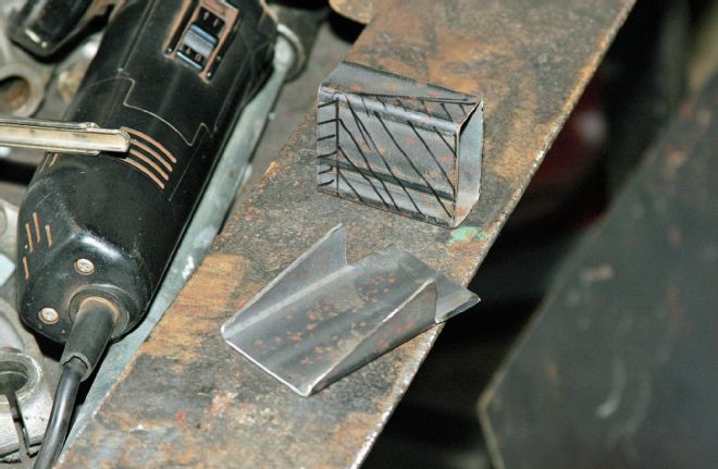
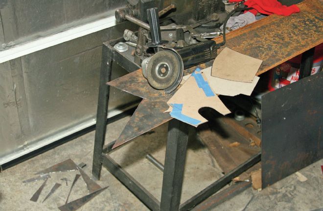 We used 1⁄8-inch plate, cut with a cut-off wheel on our angle grinder, to form the box that would hold the steering box. The 1⁄8-inch plate is plenty sturdy, but we wouldn’t want to go any thinner.
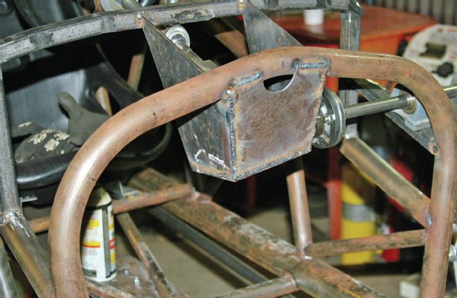 We wanted to make the steering box mount as compact as possible, to keep it away from our legs. This necessitated keeping it narrow and hanging the whole thing down from the center, rather than adding a side-to-side mounting point. We also tied it into the dashpanel’s mounting hoop, partly to help secure the box (though we could have secured it solidly to the firewall hoop alone), partly to keep the dash mount hoop from vibrating or rattling when the car is running.
 The mounting box needed a hole or a notch to clear the pitman shaft and coupler. With as tight as we made the mount to “wrap” around the steering box, we put in a notch so the steering box can easily slide in and out.
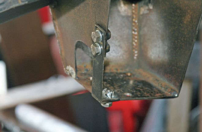 Maybe it was needed, maybe it wasn’t, but we really want the steering box mount to be as solid as possible, so we made a brace to replace the metal that was removed from the notch. Welding the nuts to the steering box mounting structure makes removing the brace a one-wrench operation. The steering box mounting bolts, the brace, the coupler, and the pillow bearing are all the same size bolts, so we only need one wrench size to work on any of it.
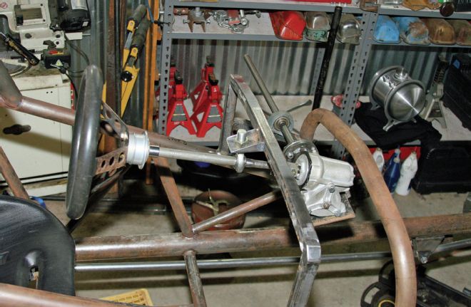
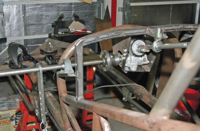 Here you see the steering box and shaft mounted. We will trim the pitman shaft during the body mounting process to keep the down-standing pitman arm as close to the outside edge of the cowl as possible. The original mounted inside the body and ran through the firewall, and we’ll do the same, but we want it to be as close as a straight line to the steering arm on the axle as possible. In the ’50s and ’60s, it was common to have the steering linkage come out of the firewall at really funky angles, which plays havoc with steering geometry. We’d like to minimize that as much as possible.
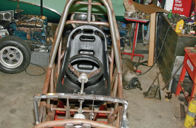 Steering, seat, and wheel in place. We didn’t weld the quick-disconnect to the steering column yet, because we want to fine-tune the column length once the car is closer to completion. There’s a balance between arm length when the driver is seated, and distance to the cowl. It might only be an inch when it’s all said and done, but in a cramped cockpit, an inch is a lot of room. We want the most room possible to facilitate climbing in and out of the car, while keeping the steering wheel a comfortable arm’s length away.
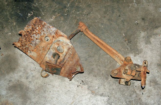 We’re toying around with the idea of using a ’54-’55 Buick under-floor mount for the brake master cylinder. Here it is, fresh from a rotted donor car at a friend’s place, with the section of floor we cut out to get to the mounting bolts from above.
 We cleaned it up and added some lightening holes to the arm. If we use this, the pedal would be up near the firewall and the master cylinder would be toward the rear of the car. The hang-up for us is whether we can integrate it into the floor structure with the under-floor bars. We’ll figure that out soon, but if we decide not to go with it, we wanted to show it as an option for our readers with other projects. You can still find ’54-’55 Buicks in old junkyards, while the early Ford under-floor setups are gone. ★
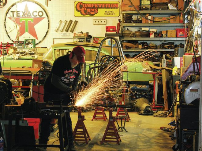
Locating the steering box was a ballet of figuring in the pitman shaft location, steering column height, and angle in relation to the driver’s position. It’d be easy with a helper and a bunch of expensive tools and a rack of extra material to mock things up, but we did the whole thing with one man, in a cluttered shop, using nothing but a cut-off wheel on a handheld grinder, a drill press, a cheap magnetic protractor, and a welder, so it’s definitely within the abilities of any backyard mechanic.
Sounds a lot like how guys built them in the old days.