While upgrading the front suspension on a classic truck has become common practice, that old leaf spring or trailing arm setup oftentimes seems to be overlooked. While either of those setups work fine for general street use, when it comes to modern performance, they're both lacking. So it should come as no surprise that when Roadster Shop redesigned the venerable Mustang II IFS for the early C10 trucks, they didn't stop there.
Instead, they designed a custom four-link setup for the rear to complement their new REVO IFS. Once again, the Roadster Shop boys designed the rear suspension components using computer aided design (CAD), allowing them to testfit the entire assembly together in a virtual state. Using CAD also has the benefit of speeding up and simplifying production, which helps keep R&D overhead down, which translates into a more affordable product. It also results in an extremely precise component, an important feature when said components are required to bolt in place using existing mounting points on a stock chassis.
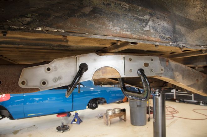
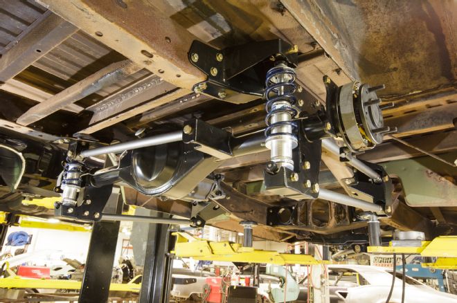
The result is a complete subframe package that performs better than stock and complements the REVO IFS. Large-diameter parallel four-bars control vertical suspension movement while an oversized panhard bar keep lateral motion in check, all hung off a Strange Engineering Ford 9-inch rearend. A pair of bolt-in frame brackets serves to strengthen the stock frame where a C-notch is necessary while also acting as upper mounts for the coilover shocks and panhard bar. Up front, another pair of brackets bolt to the stock C10 chassis and act as the front mounting point for the four-link. This compact package allows easy routing of large diameter exhaust and accepts a 10-inch-wide wheel under the stock fender.
While we're following along as Roadster Shop swaps the stock trailing arm components on their 1969 Chevy shop truck, their rear subframe is designed to drop under the early C10 trucks from 1960-72, with plans to extend the coverage into the 1973-87 market soon.
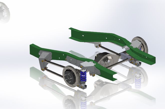
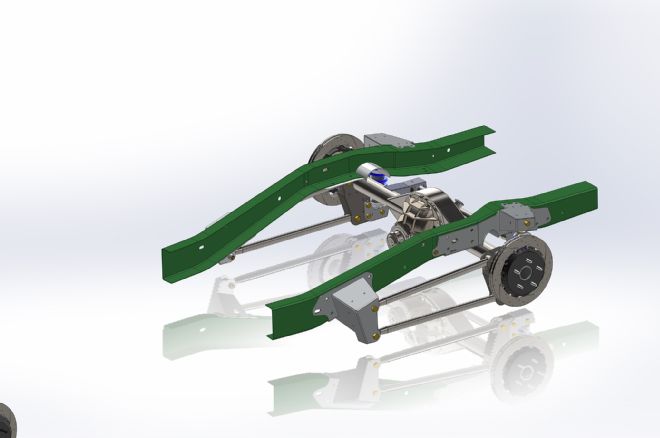
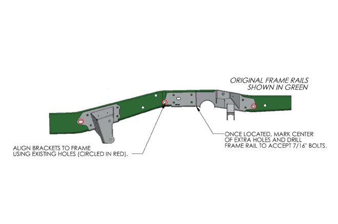
01-02 CAD drawings of the Roadster Shop REVO rear subframe components showcase their fitment on the stock chassis (in green). Utilizing a number of stock holes in the chassis, the four brackets can be bolted in place while the rest of the mounting holes are drilled, making for a trouble-free installation.
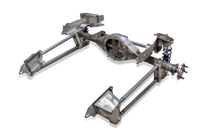
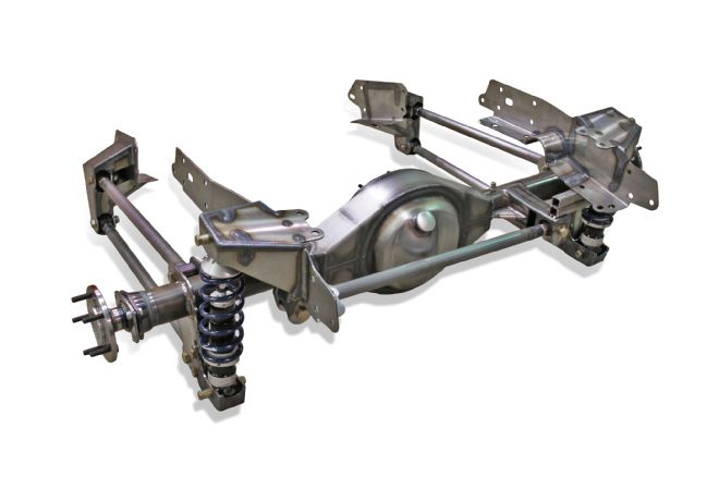
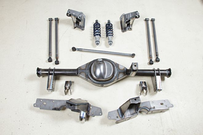
03-05 Here's the complete subframe kit in all its raw steel glory. Roadster Shop uses a Strange Engineering rearend, complete with four-link, panhard bar, and coilover shock brackets welded in place, as the foundation for their REVO four-bar rear. Bolt-in chassis brackets accept the oversized four-bars as well as the panhard bar and coilover shocks, rounding off the suspension components. Adjustable Afco coilover shocks are also standard fare.
06 As with most lowering kits for these trucks, Roadster Shop's requires a small C-notch in order to retain full suspension travel. These are incorporated into the shock mount brackets and also feature a mounting point for the panhard bar on the passenger-side bracket.
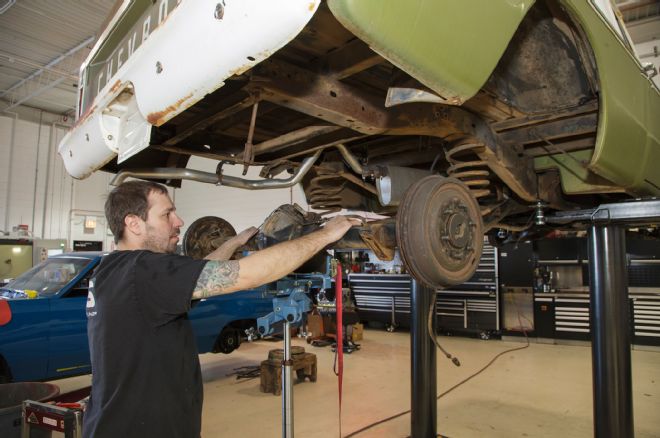
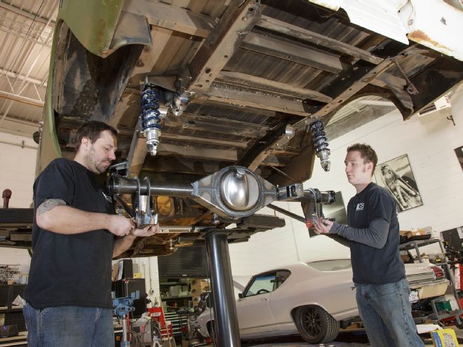
07 Before any of the Roadster Shop components can be installed, the stock suspension components need to be removed, in addition to a couple brackets on the chassis. This meant disconnecting the trailing arms, springs, shocks, brake line, and panhard rod before the stock rearend could be removed.
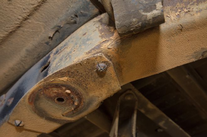
08-09 The stock coil spring mounting pads, panhard bar mounting bracket, and bumpstop brackets are all riveted to the chassis and need to be removed to make room for the new REVO subframe brackets. To do so, first two intersecting cuts are made on the head of each rivet.
10 Then, a pneumatic chisel is used to shear the head of each rivet.
11 Once the rivets are removed, the bracket can be easily persuaded from the chassis.
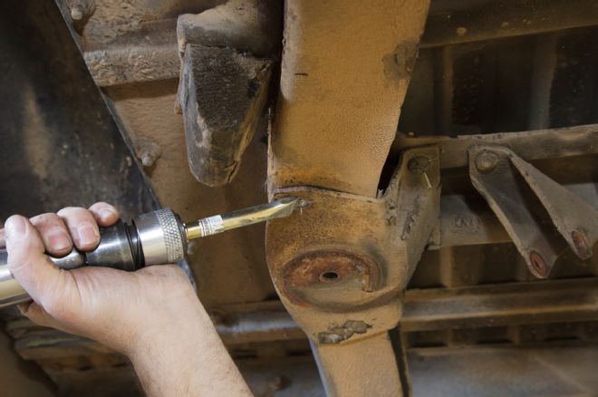
12 The REVO kit comes with a pair of framerail templates that can be clamped in place using existing holes in the chassis. The templates are then used to mark the C-notch location on each framerail.

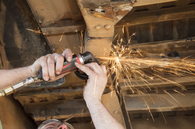
13 With the templates in place, a plasma cutter is used to easily and cleanly cut the C-notch in the frame.
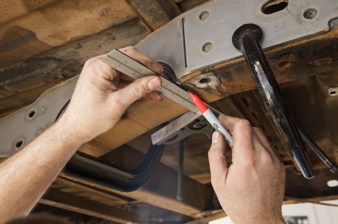
14-16 A straight edge is used to mark the underside of the chassis so that the entire C-notch can be cut and removed.
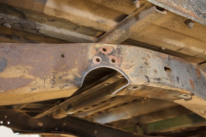
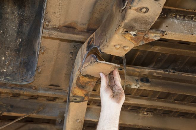
17 Here's the completed C-notch.
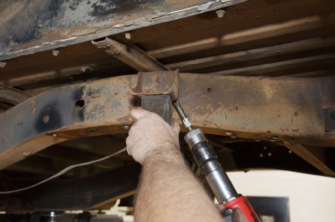
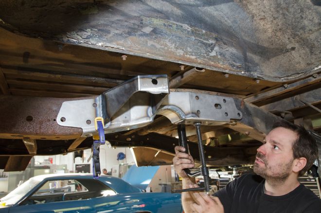
18 The four bolt-on brackets use a series of preexisting holes on the stock C10 chassis in which to locate, making installation effortless.
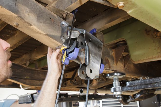
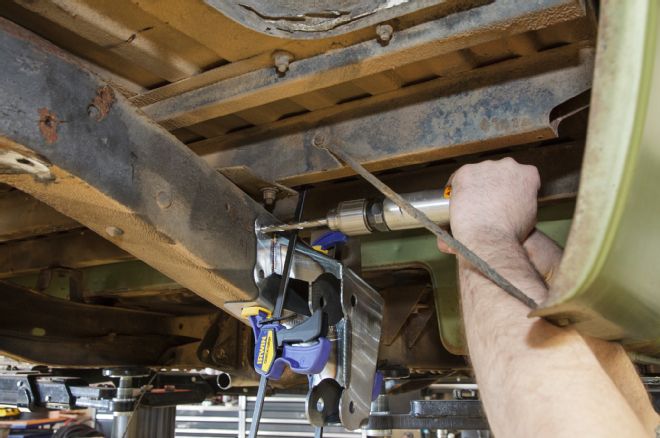
19-20 Using these reference points, the brackets are then clamped to the chassis so that a series of 7/16-inch holes can be drilled in the frame. These will serve as the mating points between the brackets and the frame.
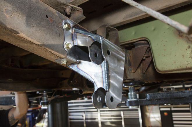
21 Here's the first bracket bolted in place.
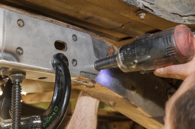
22-23 The rear C-notch brackets are installed in a similar fashion, using a hole at either end of the bracket to serve as a reference point.
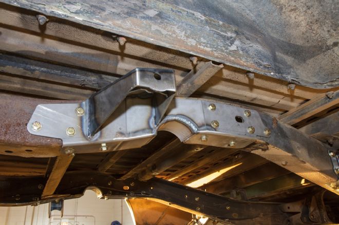
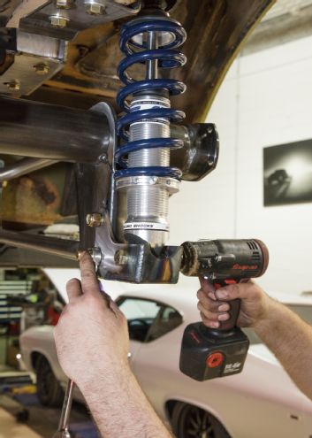
24 Once all the holes are drilled and the fasteners installed, the bracket is attached and ready for the components to be installed. Note the use of grade 8 fasteners throughout the kit.
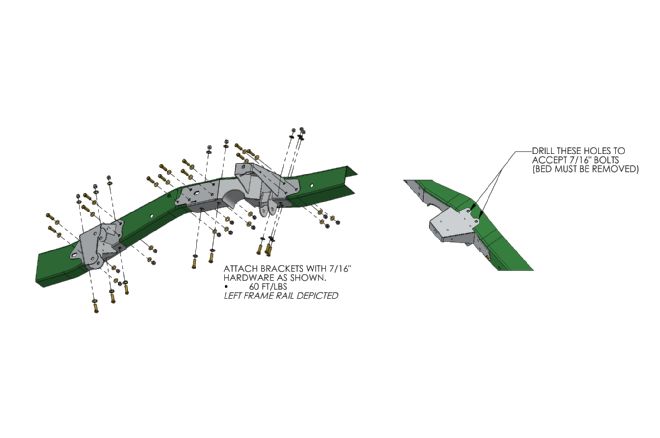
25 This diagram illustrates the attachment points for the left framerail brackets.
26 Before the rearend is lifted in place, the four-bars are loosely attached to the brackets using the provided grade 8 hardware.
27 The Afco coilover shocks are also installed prior to the rearend.
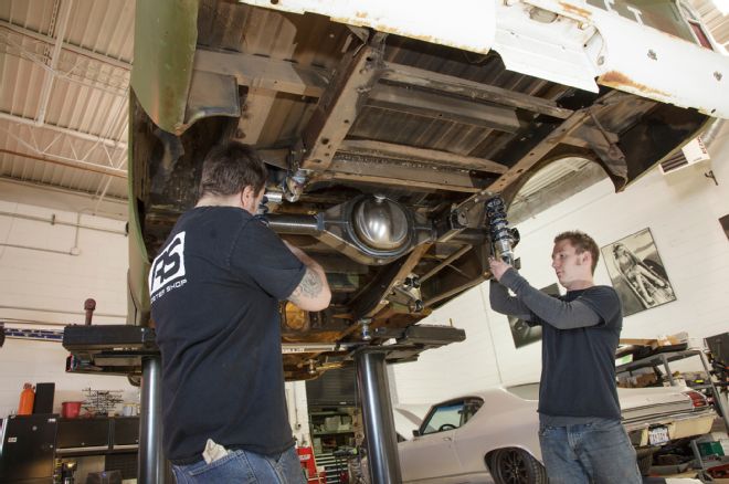
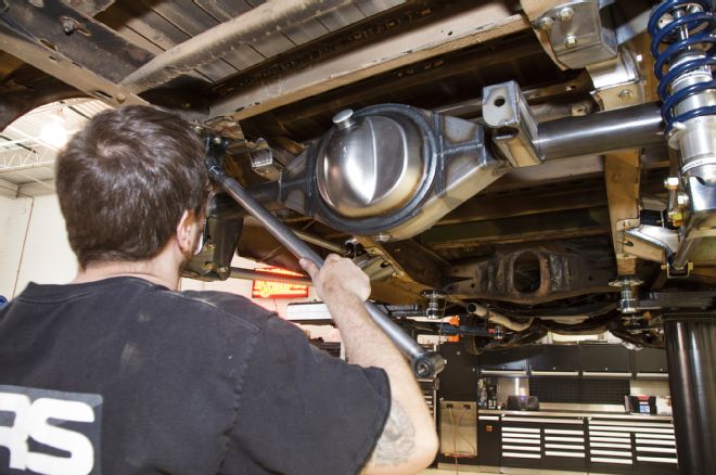
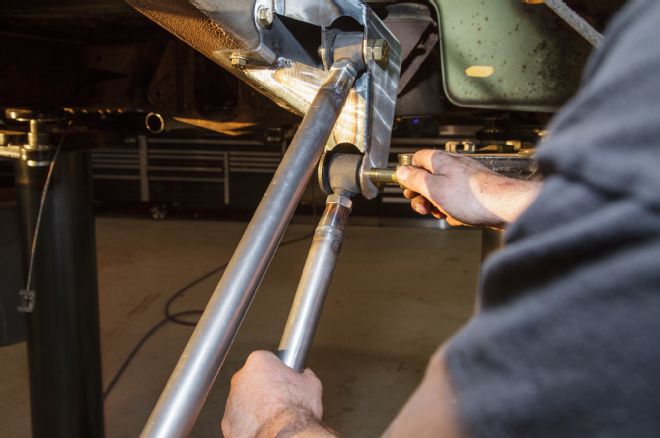
28 Next, the rearend is lifted into place and the four-bars attached …
29 … followed by the coilover shocks. The coilover shocks each attach to a bracket that is bolted to the rearend using one of two positions on the rearend axle bracket.
30 With the rearend in place, the adjustable panhard rod can be installed.
31 Since the REVO kit is a bolt-on affair, once initial assembly is complete, the entire works can be removed and sent out for powdercoating and reinstalled with ease.
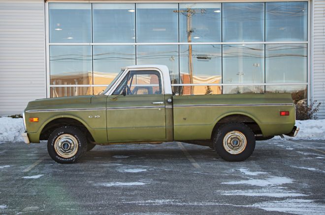
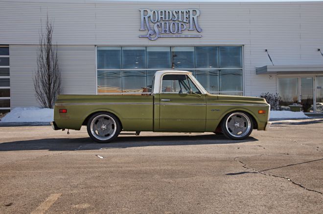
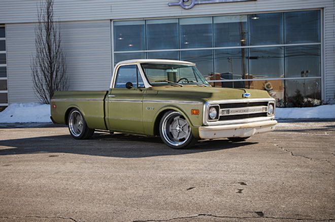
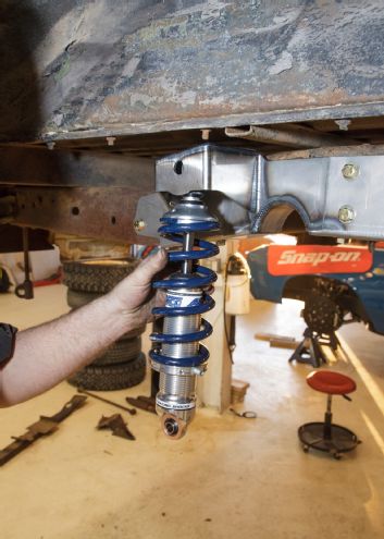
32-34 Comparing the before and after shots, it's hard to believe that the only thing the Roadster Shop boys did to the old C10 was a simple attitude adjustment coupled with new roller appointments. American Racing Salt Flat wheels, 20x9.5 up front and 20x10 out back are wrapped in Michelin Pilot Super Sport tires, 265/35R20 and 285/35R20 respectively. This is the ideal wheel/tire combo for the REVO setup and will clear stock inner fender and rear wheel tubs with no body mods required. With a mini-tub installed out back, the wheels can be increased to 12 inches to accept an even wider tire.