Getting an old truck, especially one set up with any kind of transverse axle design, to sit, stop, and handle like a contemporary car is nearly impossible without a complete overhaul of the suspension design. After all, axle frontends were designed to haul, not perform like a sports car. Thankfully, for those of us who desire a more modern approach to the way our trucks ride, there are companies like Scott's Hot Rods in Oxnard, California, who have completely redesigned the old suspension system from the ground up.
Catch up on Part 1 right here: http://www.hotrod.com/how-to/chassis-suspension/1508-lowering-a-twin-i-beam-1965-ford-f-100-part-1/
Scott's starts with a custom built one-piece crossmember with 7-degrees of caster built-in that will not only serve to locate the suspension components, rack-and-pinion steering, and motor mounts, but will also serve to further stiffen the chassis, something it desperately needs. Boxing plates with sufficient clearance for the steering, lower control arms, airbags, and sway bar are added to both framerails before the crossmember is dropped in place to help further stiffen the chassis. From there, airbag and sway bar mounts are added to complete the fabrication portion of the install.
The componentry that comes with Scott's Superslam IFS kit continues to push their redesigned theme by incorporating a fully adjustable element into their tubular control arms in the form of a rod end/clevis mounting system on the upper control arms. This clever design allows caster, camber, and toe adjustments to be made easily and precisely. Serviceable ball joints mate to the modular-style spindles, making maintenance a breeze. With over 10 inches of advertised travel and equipped with airbags instead of the typical coilover shock, our truck should be able to go from tucked to truck with ease, all while maintaining minimal camber change.
With the majority of the fabrication work completed last month, we're returning to tackle the bolt-on portion of the IFS build on our 1965 Ford F-100. We left off with the crossmember in place, ready to accept the suspension components. Once installed, it's a simple matter to locate the upper shock and airbag mounts, followed by the sway bar mounts. After cycling the suspension throughout its full travel to check for any complications, the bracketry can be finish welded and our attention can move elsewhere on our truck, confident that our frontend not only looks great, but will sit, stop, steer, and perform like its 21st century counterpart.
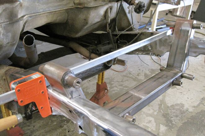
01 When we left off last time, our framerails had been boxed and notched to clear the control arms, airbags, and rack-and-pinion, and the crossmember was ready to be welded in place.
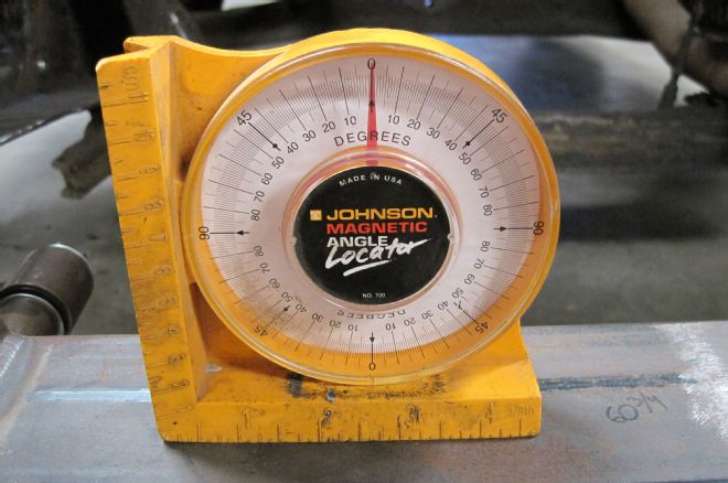
02 Before the Scott's crossmember is tacked in place, it's checked for level and alignment.
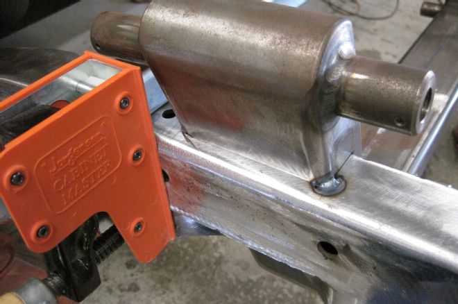
03 Once in spec, the crossmember is tacked to each framerail in a handful of locations by our buddy Danny Day.
04 With the crossmember tacked in place, we can begin installing the Scott's suspension components, starting with the lower control arms, identifiable by the lower airbag mounts. That's the sway bar mount jutting off the front of the control arm; this should be oriented to the front of the truck.
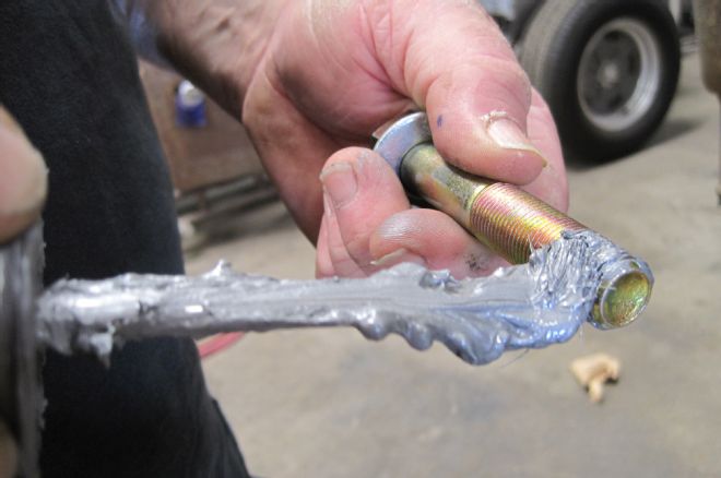
05 Anti-seize lubricant should be used throughout the install to prevent galling of the hardware.
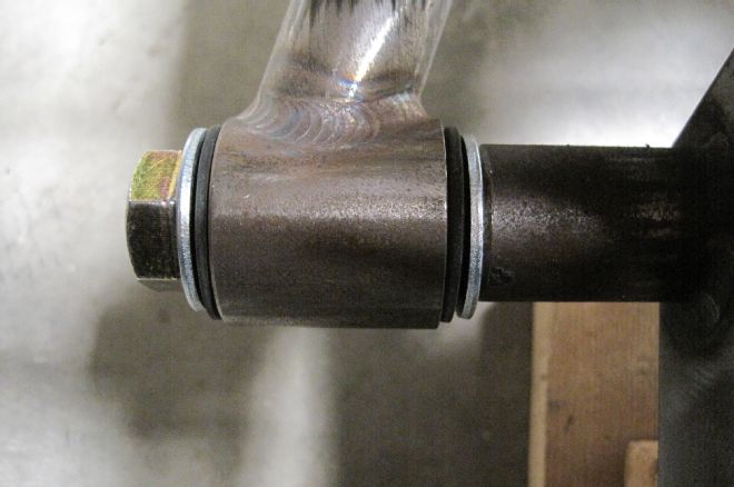
06 Note the spacers on either side of the control arm bushing. This keeps the bushing in place and prevents it from being squished if the bolt is over-tightened.
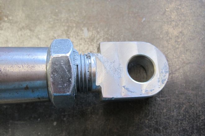
07 The tubular upper control arms utilize a rod end on either side for easy toe adjustment. For initial setup, the rod end is turned all the way in, then back out five full turns.
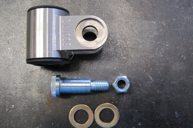
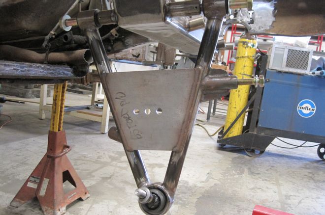
08 Both rod ends are in turn held in place by a clevis, fastened by a shoulder bolt, with two washers on either side of the rod end and secured with a Nyloc nut.
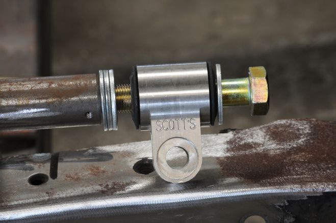
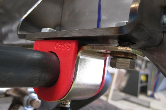
09 With the Scotts logo pointing out, the clevis is attached to the crossmember using a single washer on the bolt side and three on the crossmember side. These washers will be added or removed later to finalize our caster adjustment. Once it's finalized, a set screw will secure each control arm bolt.
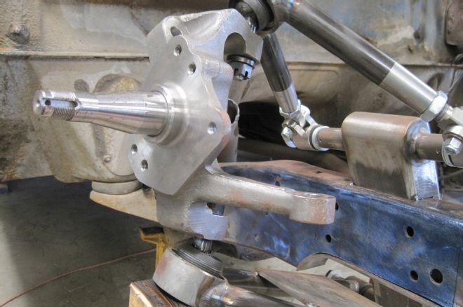
10 Here's the tubular upper control arm assembly, complete with the serviceable ball joint installed.
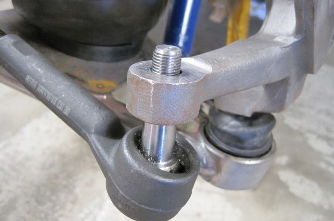
11 Next we attach the spindle to the A-arms and secure it with the appropriate spacer and castle nut.
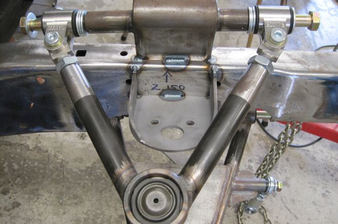
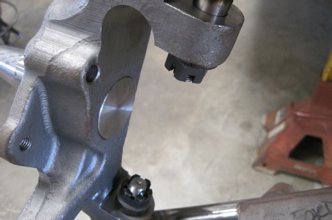
12 With both A-arms and the spindle in position, we need to simulate a full drop. The lower control arm is lifted until the ball joint contacts the spindle, this is the upper most travel position, simulating full drop. In its travel, the arm should make a full cycle without any interference. Note the notch on the bottom of the framerail that gives the lower control arm plenty of clearance.
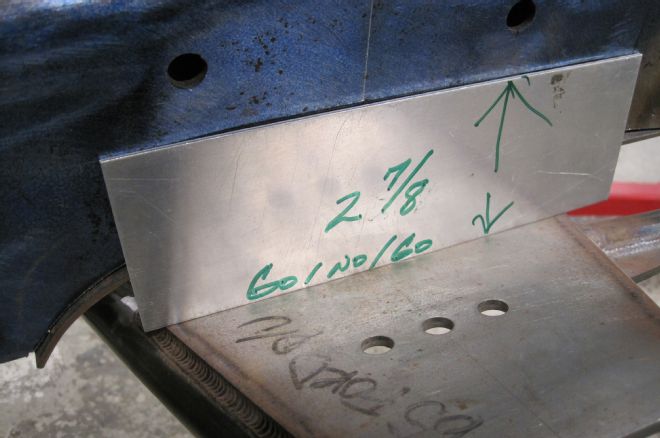
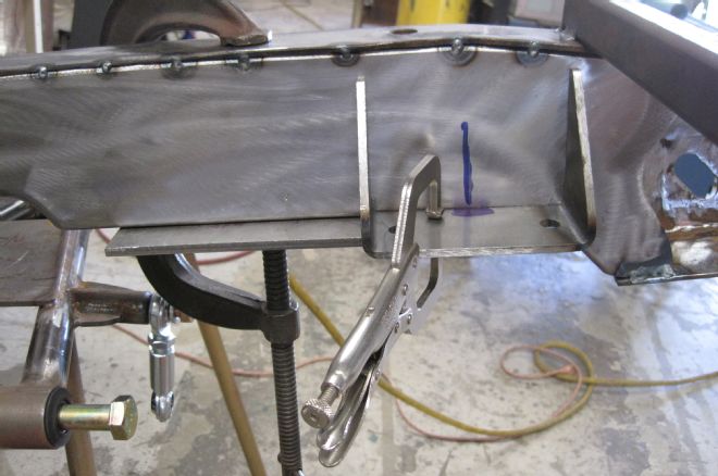
13 With the A-arms still in the most upright position, we need to mark the framerail 2 7/8-inches up from the top of the airbag plate. A piece of aluminum trimmed to spec is used as a template. This will be the bottom of the upper airbag bracket.
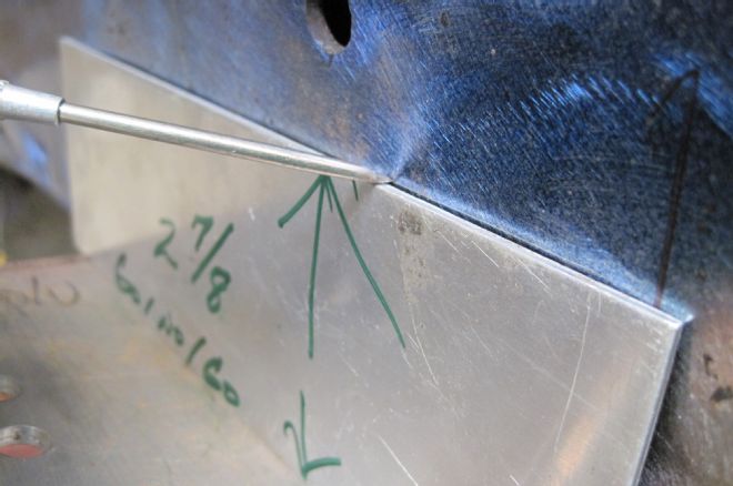
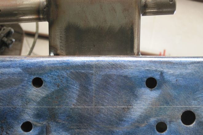
14-15 A metal scribe is used to mark the location (horizontal line); also note the axle centerline mark, which will be used to locate the center of the airbag bracket.
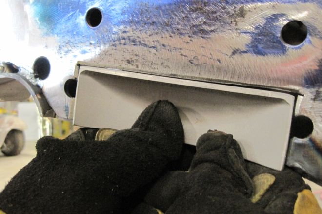
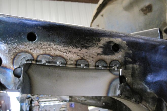
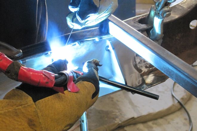
16-17 Before the air bag bracket is tacked to the frame, the framerail needs to be further notched and a provided metal box section welded in place to provide clearance for the airbag.
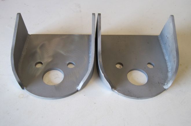
18 Here are the two upper bag mounting plates, which will be welded to the frame.
19-20 Using our prescribed lines, each bracket is tacked in place.
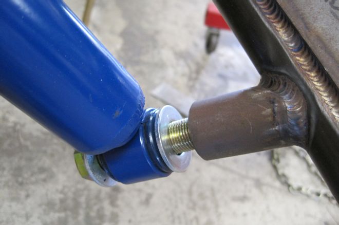
21 Next, the upper shock brackets need to be installed. First, the shocks are fully compressed and a piece of string is used to secure it. The string is tied so that the shock will remain compressed (wire can also be used). Then the compressed shock is attached to the lower control arm shock mount.
22 The upper shock bracket is then attached to the upper shock stud; note the arrangement of the bushings and washers.
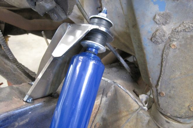
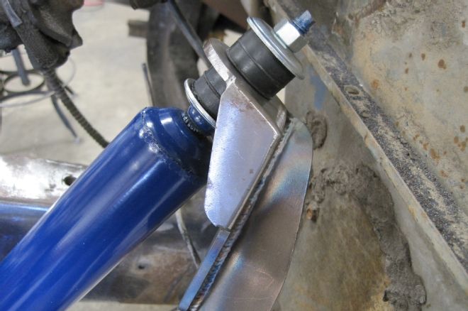
23 Per Scott's instructions, the upper mount will lays in its natural position when the shock is fully compressed. The mount will be closely pre-angled to sit in the correct position, then tack welded in place.
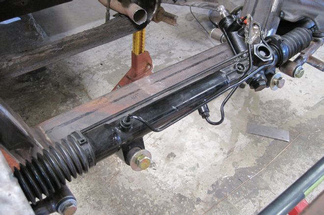
24 Installing the power steering rack in next, using two 5/8-inch fasteners to attached it to the crossmember. Note the C-notch clearance on the framerail for the tie rods.
25 With the rack-and-pinion centered in its travel and the spindles in line relative to the chassis, the outer tie rod ends can be adjusted until they slide into each steering arm and fastened with a castle nut/cotter pin, completing the basic component assembly.
26 Each airbag will mount between the lower control arm and the upper frame bracket.
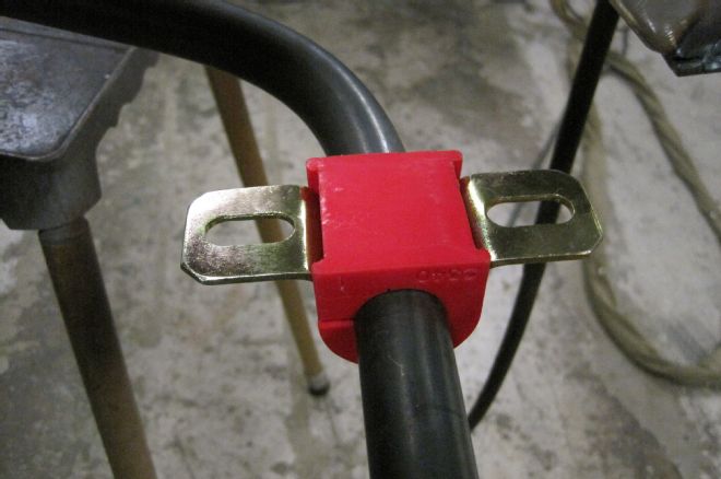
27 The sway bar requires two brackets be welded to the inside of each framerail to secure it in place. To locate these brackets, the sway bar needs to be attached to the lower control arms using the provided Heim joints and hardware.
28 With the sway bar installed, it's lifted until it contacts the bottom of the frame, where a vertical mark is made on the side of the framerail. The sway bar brackets are then clamped in place using these marks. Note that the bottom of the bracket is even with the bottom of the framerail.
29 Each sway bar bracket is then tacked in place.
30-31 Next, the bushings are installed on the sway bar, the sway bar ends once again attached to the lower control arms, and the bushings bolted to the frame brackets.
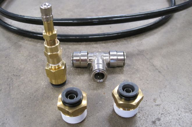
32 To allow us to temporarily test our airbag setup, we picked up some 3/8-inch push-lock fittings and a couple feet of hose that will be plumbed to a "T” fitting, topped with a Schrader valve. This will give us the capability to inflate and deflate our system to ensure free and clear travel of the suspension components before any final welding takes place.
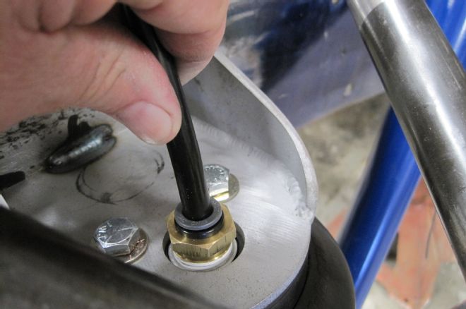
33 Once attached to the upper and lower brackets, the airbags are plumbed using the push-lock fittings.
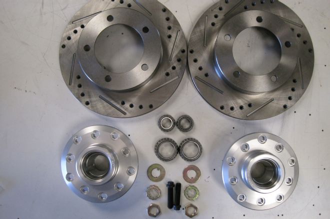
34 It wouldn't be a proper upgrade if we didn't opt for large disc brakes, so we decided to have Scott's spec our frontend using CPP's drilled and slotted 11-inch rotors and aluminum hubs.
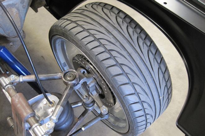
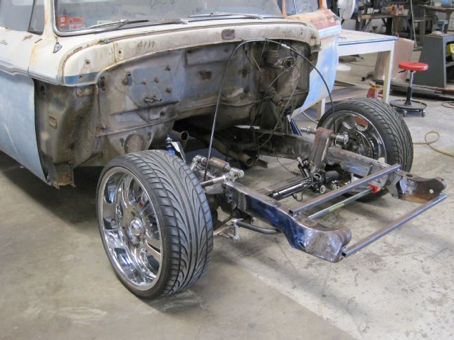
35 Once we finalize wheel size, we'll determine our caliper clearance, but for now our F-100 is situated on a set of rollers for the time being.
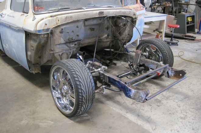
36 With the truck back on the ground and the air bags inflated to simulate ride height, our F-100 is starting to look like a proper street truck! Deflated, our truck drops the rockers nice and low.