When it comes to lowering a classic truck, it seems that the job is divided into two camps: the simple and the difficult. Trucks equipped with an independent suspension setup from the factory, such as the 1967-72 Chevy C10s, are of the simple variety. That is, the components needed to modestly lower a truck are all bolt-on. Drop spindles, springs, and shocks are all items that are readily available and replace their stock counterpart with no fabrication required. Other trucks, such as those equipped with either a straight axle or the long-running Ford twin I-beam design, are a different story. To really achieve a proper drop with contemporary suspension accoutrements, it's necessary to get rid of the original suspension design. That usually means that anything that bolts to the chassis forward of the firewall needs to be binned, including the crossmember. This results in a lowering job that is much more difficult, with a bit of talent required (i.e., fabrication and welding skills).
There is a silver lining however in that once the job is done not only will you have a lower riding, and arguably better looking, truck on your hands, but if you use a kit from a company like Fatman Fabrications, you'll have a truck that rides, stops, and steers better than anything that left the factory that same decade.
We've made a few upgrades in the past on our buddy Danny Valenzuela's 1969 Ford F-100 and one thing he always bugged us about was lowering his stock, longbed hauler. Knowing that bolting on a pair of lowered I-beam axles wouldn't result in the contemporary suspension geometry that he desired, we opted to contact Brent VanDervort at the aforementioned Fatman Fabrications. What Brent recommended was their Mustang II-based IFS kit that would not only get rid of those heavy, swingin' I-beams, but it would also upgrade the stock drums brakes to disc (though in our case we had already installed a set on the original I-beams). The stock steering box would also get set aside in favor of a power rack-and-pinion setup, a must on these trucks. For our project, we'll be using the tried-and-true coil spring option, though Fatman offers coilover and air ride setups as optional upgrades for those who desire truly trick suspension components. All of this trick stuff will also give us a 6-inch lower ride, not a bad package if I do say so myself!
Though it does take some fabrication skills to install a Fatman Mustang II kit in a 1965-79 Ford truck, the majority of the modifications can be done in a day with a simple MIG welder and a four-inch grinder. We'll be using a Millermatic 211 for all the welding requirements on this install, coupled with their Spectrum 625 X-Treme plasma cutter. If you've never used a plasma cutter before, it makes tasks such as this truly a breeze.
This month, we'll cover the fabrication portion of the suspension job, followed by the bolt-on components next month. We'll wrap up with a flip-kit install out back to get both ends of the truck sitting nice and low atop a rebuilt, stock 9-inch Ford rearend. Be sure to follow along to see what it takes to drop a twin I-beam Ford!
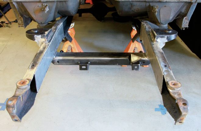
1. Here are the Fatman components that we'll be installing this month. The new crossmember replaces the stock unit and locates the lower control arms and rack-and-pinion while the shock towers will locate the upper shock and coil spring mounts as well as the upper control arms. Four gusset plates will be used to strengthen the shock towers.
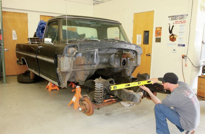
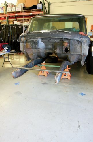
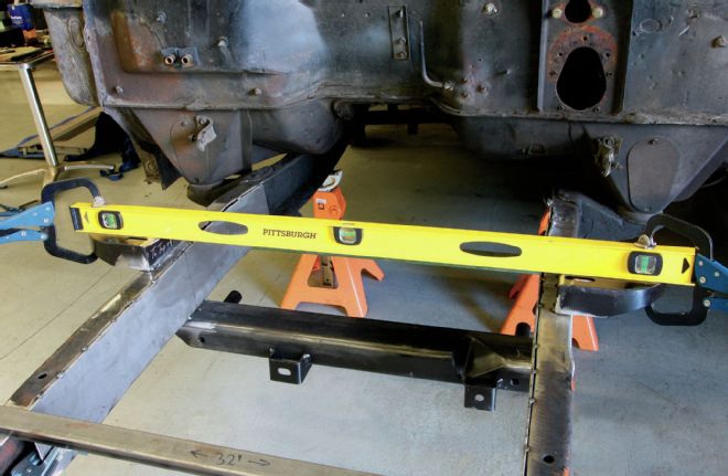
2. Arguably the most important part of the entire install is the proper setup of the chassis before we even get started. Since we'll be removing the stock suspension components, if we don't set up some baseline measurements before we get going, things will go downhill fast. First, the truck is lifted and set on jackstands, installed at all four corners. Next, the chassis is checked for level, side to side, with the corresponding jackstand shimmed if needed. It's a good idea to check for level at more than one location as well to make sure the frame isn't twisted.
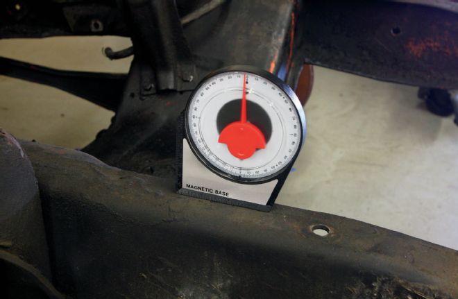
3. A 2-3 degree forward rake is more or less industry standard spec, so we set up the chassis to reflect this measurement as well before we get started.
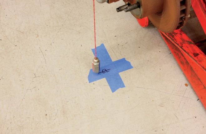
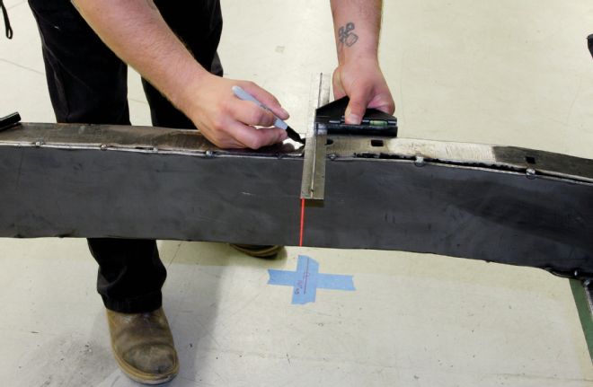
4. The next step is to mark the axle centerlines. I like to do this using two methods, consider it a combination of old and new. First, I use a string and plumb bob to mark the location on the shop floor.
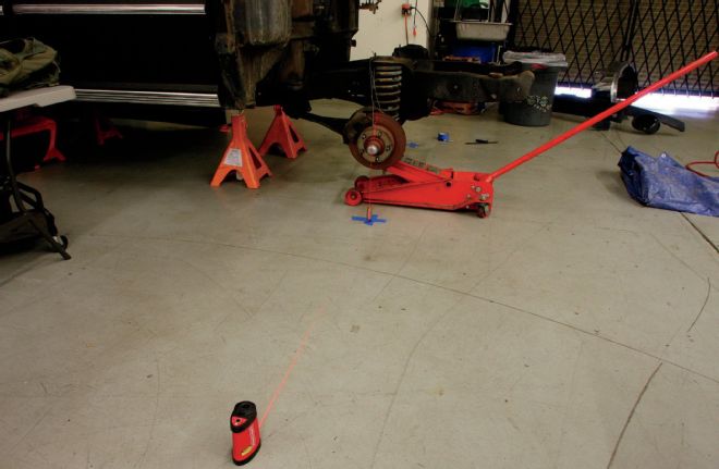
5. I also use a laser level lined up with the string and plumb bob as it will project a line through to the other side of the chassis. This isn't so important at this point, but once the opposite side's axle centerline is determined, I can use the laser level to compare the two to ensure the axle centerline is square to the chassis.
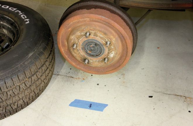
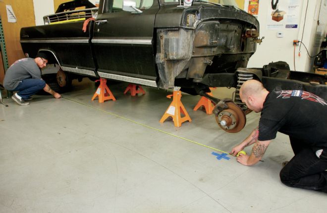
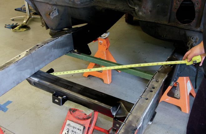
6. I also like to take the time to mark the rear axle centerline as well. This allows me to measure the wheelbase to be sure our plumb bob specs are within factory parameters (131 inches for a longbed). Once the axle centerlines are marked and everything looks good, the front suspension components can be removed.
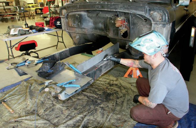
7. The last bit of preparation necessary before we get started is to tack weld a few pieces of stiff steel tubing or angle iron across the framerails. This will ensure that the 'rails don't twist, rise, or dip out of level when the crossmember is cut free and the new crossmember is welded in place.
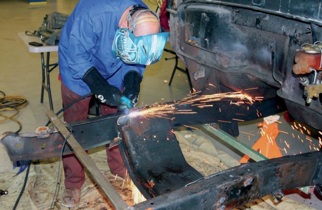
8. Now it's time for the fun bit! Using our trusty Miller 625 Spectrum X-Treme plasma cutter, I set off trimming the fat away from our Ford chassis. If your truck is as greasy as ours, do yourself and anyone within a country mile a favor and grab a couple fans to blow the offending smoke out the door. I also like to keep an air hose with a blower attached nearby to help extinguish any small fires that might erupt (they will!).
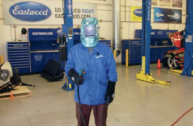
9. The obligatory safety shot. Usually when I use the plasma, I can get away with using my tinted safety glasses, but I recently upgraded to a Miller Digital Elite helmet and found that its added protection along with its capability to auto-darken in “cut” mode makes it pretty handy for these big plasma jobs.
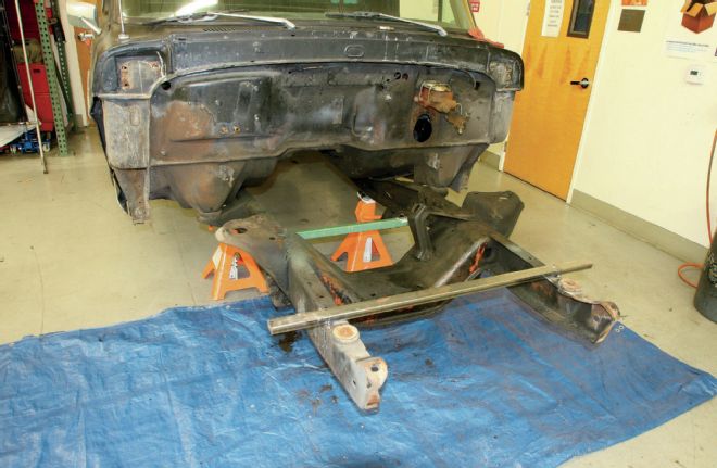
10. With the crossmember and coil spring towers removed, we're now past the point of no return. No worries, right?
11. The stock Ford truck frame, while plenty strong, isn't exactly stiff. This is one of those frames that can really benefit from a boxing job and that's exactly what we're going to do. I picked up two 36x12-inch sheets of 1⁄4-inch steel to do the job. I clamped each to the corresponding framerail before tracing the shape onto the plate.
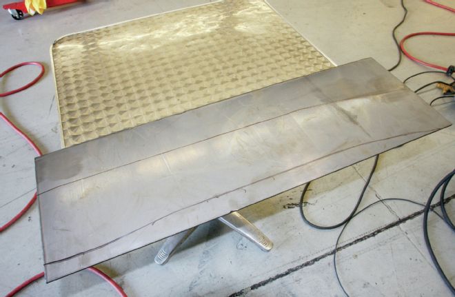
12. While 1⁄4-inch is a bit overkill for boxing plates, I had the ability to cut it and that's what the metal yard had in the remnant pile, though 1⁄8- or 3⁄16-inch plate would be fine. Here's the traced pattern, ready to be cut with the plasma.
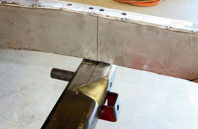
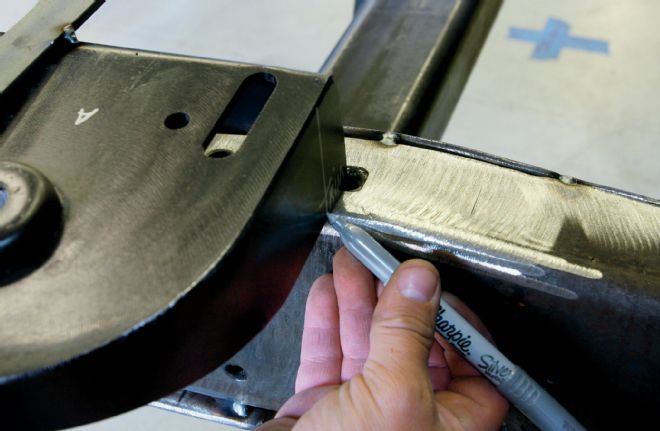
13. With the framerail marked, the new crossmember can be lifted into place and centered in the chassis. The axle centerline corresponds with the center of the crossmember. I like to measure five times and cut once, so here I'm taking diagonal measurements to ensure that the crossmember is nice and square before I tack it to the framerails.
14. With the boxing plates tack welded to the framerails this is where the laser level really helps out. When set across the two axle centerline marks, it projects a vertical line that makes marking the axle centerline on the framerail a piece of cake.
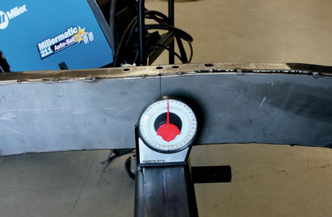
15. Since the chassis is setup at the approximate final rake, the crossmember can be plus or minus one degree of level. I opted to shim the back of the crossmember just a touch to get it closer to level as the bottom of the frame curves slightly downward towards the front of the truck.
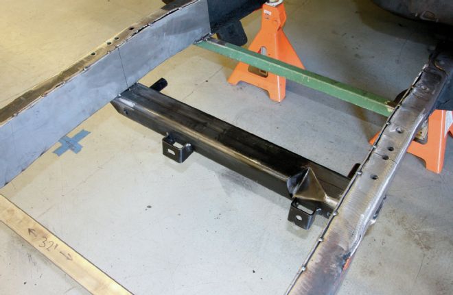
16. With everything triple checked, I tacked it into place. Note that the boxing plates haven't been fully welded at this point. I decided to wait until the crossmember was in place before putting too much heat to the chassis, just in case it decided to twist or get out of shape.
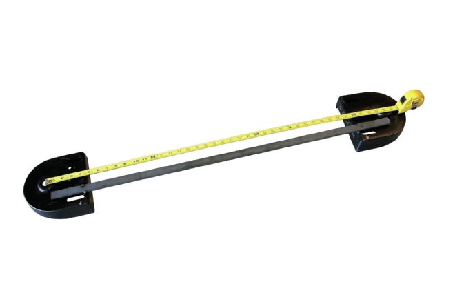
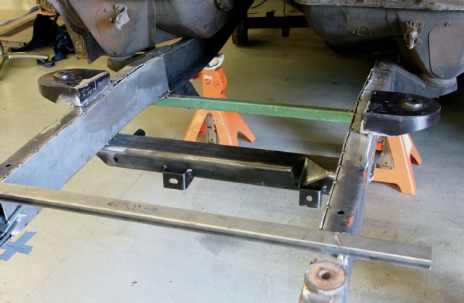
17. Next, it's time to install the shock towers. These need to be installed exactly 40 inches apart, as measured at the shock mounting holes. A piece of steel is used to retain the distance, tacked to each tower. It's important to also ensure that they are nice and even in relation to each other as well since they'll be installed on the chassis exactly as they sit.
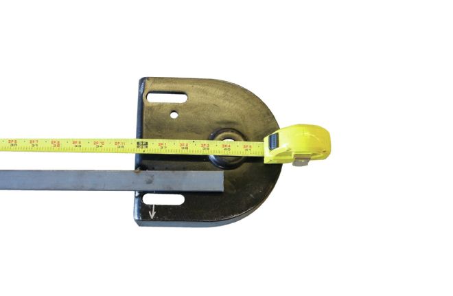
18. Since frame widths can vary, the rear corner of each shock tower needs to be trimmed so that they can fit over the framerail perfectly. Before I placed the shock towers onto the chassis, I marked the center of each, which corresponds with the shock mounting hole. When the shock towers are trimmed and placed on top of the framerail, the alignment of the centerline mark on the bottom of the shock tower and the centerline mark on the framerail will ensure that the built-in anti-dive angle of the shock tower is retained, placing the shock hole centerline slightly rearward.
19. I first tacked the bottom edge of each shock tower to the top of the framerail before removing the jig that we installed a few steps back. Then I used a four-foot level to ensure that the shock towers were perfectly level before tacking the sides of each shock tower as well.
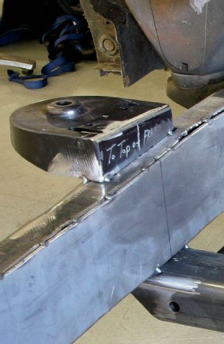
20. You can see the angle of the bottom of the shock tower that Fatman set up from the factory in order to simplify the installation and ensure that the suspension retains an anti-dive characteristic.
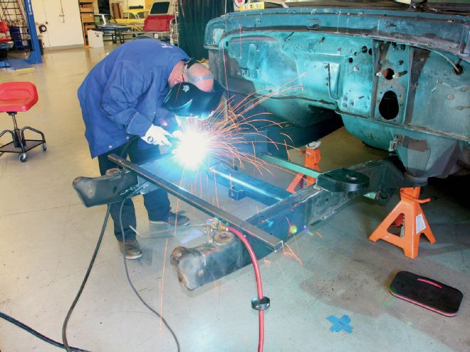
21. At this point, it's time to put the gloves, jacket, and helmet back on and get to welding. I'm going to leave the sections of tubing tacked to the framerail until we're done welding, just in case.
22. After an hour or three of welding and grinding, we're almost ready to start bolting on suspension components. Note the absence of those two pieces of tubing tacked to the frame at this point as well as the gussets I added to the bottom of the shock tower.
23. I hit the chassis with a coat of flat black as I thought we were done with the fab work, but I forgot one important step; the framerail C-notches for the rack-and-pinion steering. These are necessary in order to give clearance to the rack-and-pinion steering on lowered setups such as ours.
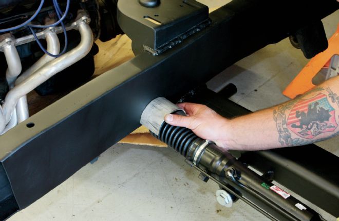
24. First, the steering centerline is determined with the rack-and-pinion installed on the crossmember.
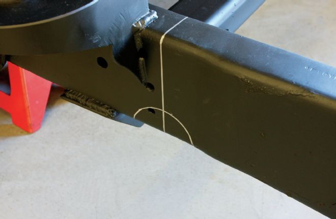
25. Then, the shape of the provided C-notch is traced onto both sides of each framerail so that it can be cut out using a plasma cutter.
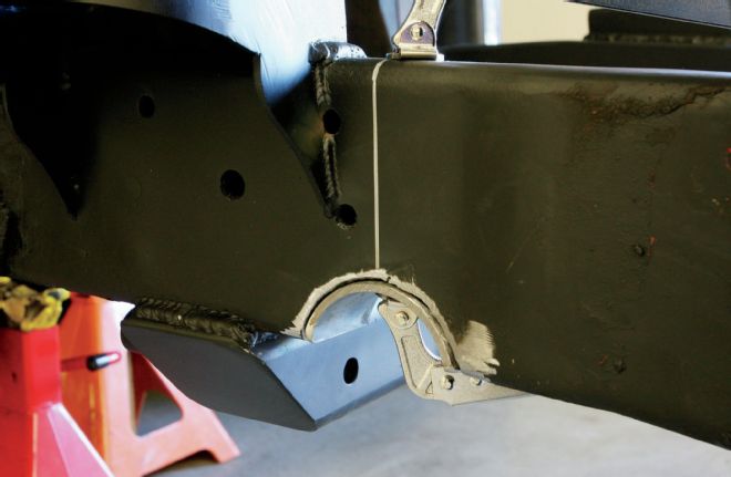
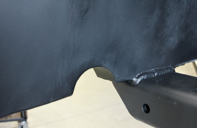
26. With the steel trimmed away, the C-notch can be clamped in place and welded up.
27. A few minutes cleanup with a grinder leaves the C-notch area looking nice and clean. At this point, we're ready to start bolting up those new suspension components next month.