This project got started when we swapped a set of old Stewart-Warner gauges for a pair of 1932 framerails and a front crossmember. An idea took shape to build a 1929 roadster on 1932 'rails and use the good Flathead V-8 engine we took out of our previous project, a 1932 five-window, which now has a 331 Caddy engine. To ensure an easy-to-drive hot rod that will keep up with modern freeway speeds, our choice of transmission is a Chevy S-10 five-speed. The rearend is from a '40 Ford, modernized with 9-inch axles and Lincoln brakes (see R&C Dec. 2011 issue, or search "Banjo Lessons" in the tech section of our website. –Ed). The frontend is a dropped I-beam, but with the spring behind the front axle, so the axle will be in front of the crossmember, something that dates back to the '40s, and was used to great effect by Doane Spencer. As so many times before, most ideas have already been done, but they are still good.
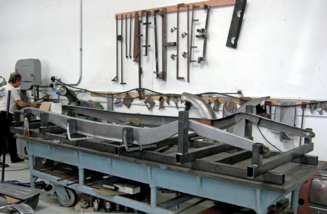
Scandinavian Street Rods (SSR) in Huntington Beach set up our framerails in the jig and began to tack everything together. But the first step was done before that by cutting the framerails to get the higher kick-up. The center crossmember was made by SSR and also the boxing plates in front of and behind the center crossmember. To keep the frame straight, a piece of tubing was welded between the rear framerails because the rear crossmember needs to be fitted later. With the basic frame together, it was taken to Roy Fjastad Jr. at West Coast Street Rods, where the rest of the modifications were done.
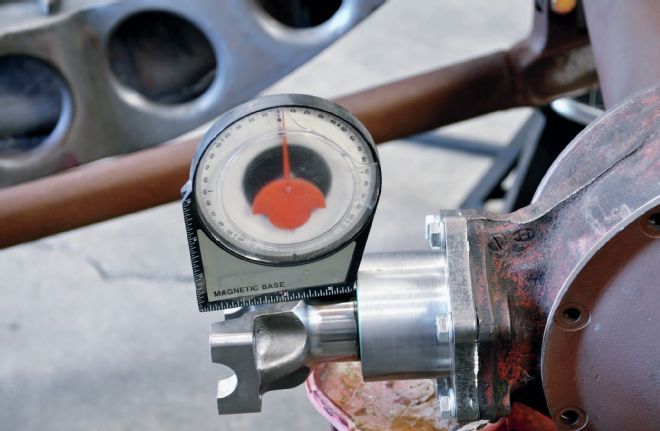
One of the important tools at this stage was the angle-finder, absolutely necessary to correctly install both the front and rear axles, plus later for the engine and trans. All the angles and measurements had been taken with the same size wheels and tires that will be used on the finished car. To hang the front spring we had help from Karl Jonasson at Foose Design, who machined the holes in the wishbones and made a pair of sleeves to mount the perches through them. With the spring installed, the shackles should have a 45-degree angle with everything in place, including the engine and trans.
Threaded bungs were welded into the split wishbone ends to accept tie-rod ends while on the frame, another pair of bungs were machined with the correct Ford 7-degree taper to accept the tie-rod ends. Once the frontend was checked to ensure the caster angle was correct, the framerails were marked and drilled out to 1¼ inches for the weld bungs.
1. The framerails from Shadow Rods are delivered in two pieces to make it easier to ship. These 'rails have a more distinct and original style reveal in the sides. Here the 'rails are welded together in the middle in the jig at SSR.
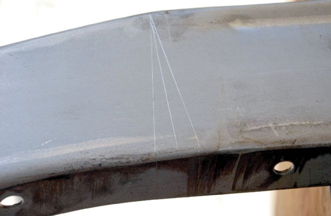
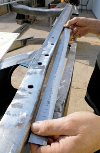
2. To get the extra 4 inches of kick-up in the rear the angles were checked on a piece of wood before any cuts were made. A V-cut, 1-inch wide at the top, gave us the 4 inches of kick-up.
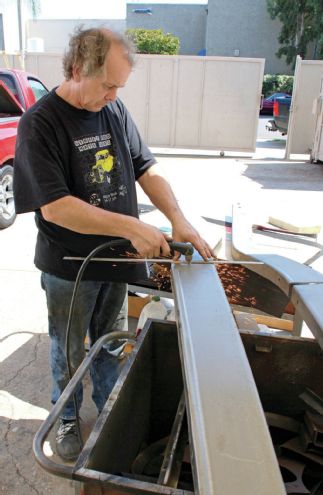
3. Erik at SSR made the cuts in the 'rails with the plasma cutter, which makes for a quick, clean cut.
4. To better fit the '29 Ford roadster body the frame was "pinched" at the firewall to 30¼ inches, which gets the frame to the fit the shape of the body and not stick out a ½ inch on each side. The front horns were also pulled in to put the 'rails inside the Deuce grille shell.
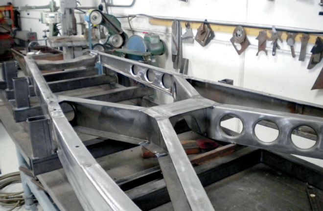
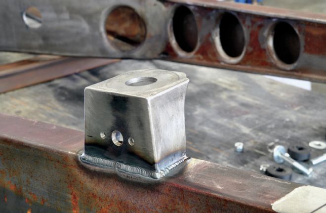
5. With the framerails in the jig it was time to weld in the center crossmember and the boxing plates in the front and rear. With the heavy '34-style center crossmember, the frame is strong enough for any type of engine/trans combination.
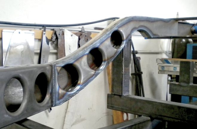
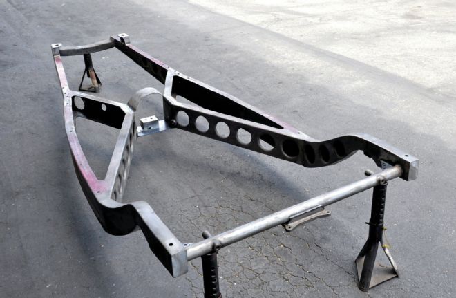
6. Once boxed, the framerails are much stronger and with the holes in them it will be easier for us to route the brake and fuel lines through the frame.
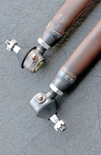
7. Weld-in threaded bungs at the rear ends of the split front wishbone accept tie-rod ends.
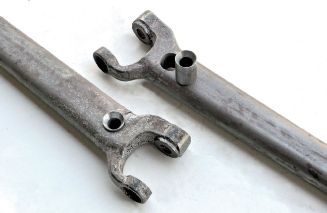
8. The front wishbones, bored and with sleeves machined to accept the spring perches. These were TIG welded in place.
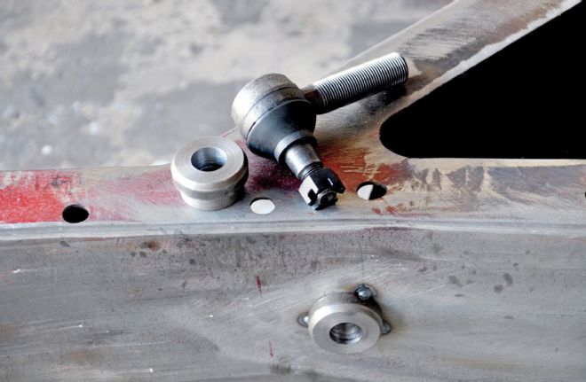
9. We had bungs machined with a 7-degree taper to accept the tie-rod ends, then welded them through the framerails. Here's one tacked in place.
The 1940 Ford rearend we are using for this project had already been modified. A 1936 Ford wishbone was bought on eBay for a cheap $85, which normally is not that easy to get for a good price. When it came to the rear crossmember, we had a choice between a So-Cal Speed Shop tubing type with brackets all pre-welded or a 1932 Ford rear crossmember. We had both, but opted for the So-Cal version because it was easier than modifying the 1932 crossmember, and it will give us more space in the rear for an exhaust system.
Just like the frontend, the rearend had to be checked for the correct angle too, as while the pinion angle could be set depending on where the wishbone brackets are welded, the spring mounts to the wishbone ends, and needs to be perpendicular to the ground. We drilled the holes in the back of the center crossmember on each side for the tie-rod bungs. We made sure to drop the frame down on the rubber stops on the rearend to check that nothing else was hitting. With the new rear crossmember in place, the framehorns were removed and the ends of the frame blanked off.
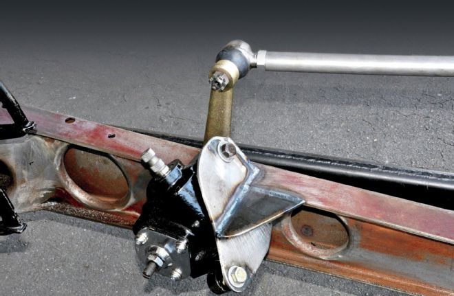
With the chassis now on its wheels, the engine and trans install could be tackled. With such a low-slung framer and minimal ground clearance, the engine would be mounted higher than normal in the frame. This presented further problems, providing minimal foot room in the small 1929 roadster body, so plenty of measurements were taken at this stage. With the engine and trans hanging in the chassis, we measured how high we needed the engine mount brackets to be, and still allow ground clearance for the oil pan. With the front crossmember moved 2 inches forward, we could move the engine 1 inch forward, to get a little extra space by the firewall but still have space in front of the engine. Once the intake manifold angle was checked, as well as the position of the trans mount, we made cardboard templates of the mounts, transferring them to sheetmetal, and welding inside and out, so they could be ground smooth. We decided to use a Vega steering box, but mounted to accept a Pitman arm, not as cross-steering. A modified Vega bracket was used to mount this.
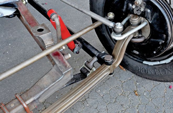
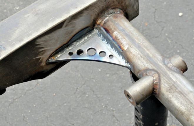
10. Moving ahead slightly, tabs were welded to the wishbones to mount tube shocks, attached at their upper end to modified F-1 Ford truck shock mounts. It's also clear here how the front spring perches mount through the 'bones.
11. Moving to the rear, these simple ¼-inch brackets were fabricated to attach the split '36 'bones to the rearend housing. (We would advise that though the 'bones will now act like ladder bars, they're not really strong enough to be used in this way with an open driveline, and suggest adding upper links or a torque arm, too. –Ed.)
12. Everything was mocked up and checked for measurements before anything was tacked in place. We ensured the rearend was straight and central in the chassis and with the required pinion angle. In our case it was 2-3 degrees negative.
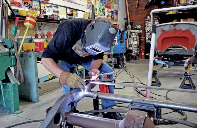
13. The rearend brackets were welded a little at a time, to prevent excessive heat buildup, and hence warping of the rearend housing.
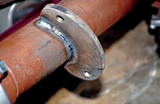
14. Roy Fjastad Jr. at West Coast Street Rods tack welded the rear crossmember after it was checked for position and angle.
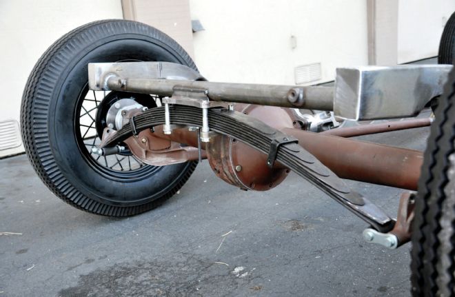
15. The rear spring is actually a front spring from a '40 Ford, which will give the roadster a softer ride than if we used a Model A rear spring. The rear crossmember from So-Cal Speed Shop will give us more space in the rear for an exhaust system.
16. Gussets were welded at each end of the rear crossmember. These pre-fabricated gussets are available from metal supply houses in different sizes.
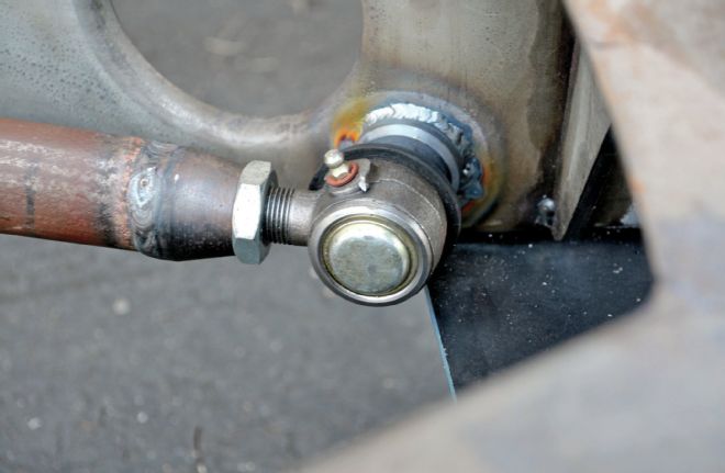
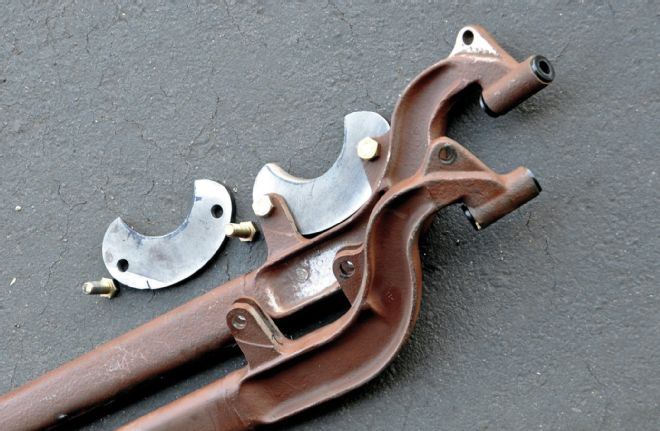
17. The split '36 rear wishbone also mounts using tapered weld bungs in the ends, but machined to accept bigger ¼-inch tie-rod ends, the bungs welded into the center crossmember.
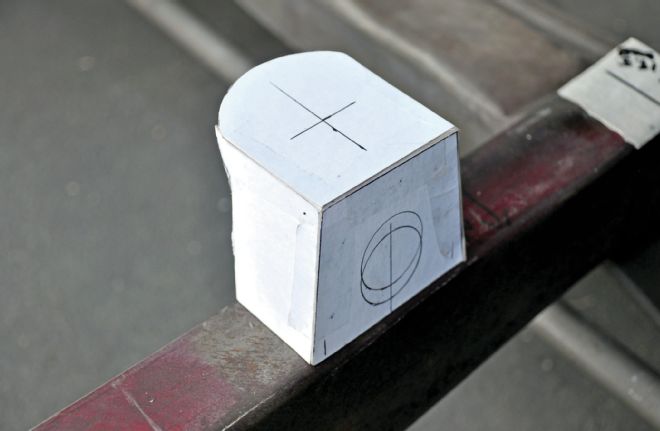
18. Engine mount towers were made in cardboard first, to determine the shape and position, then the template transferred to steel plate.
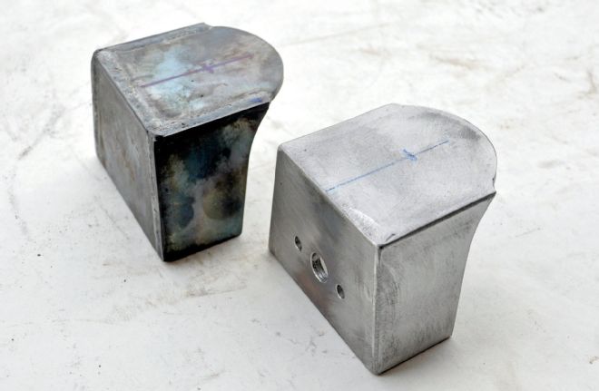
19. Fjastad Jr. fabricated the towers, welding them inside and out so they could be ground down to a smooth finish with no loss of strength.
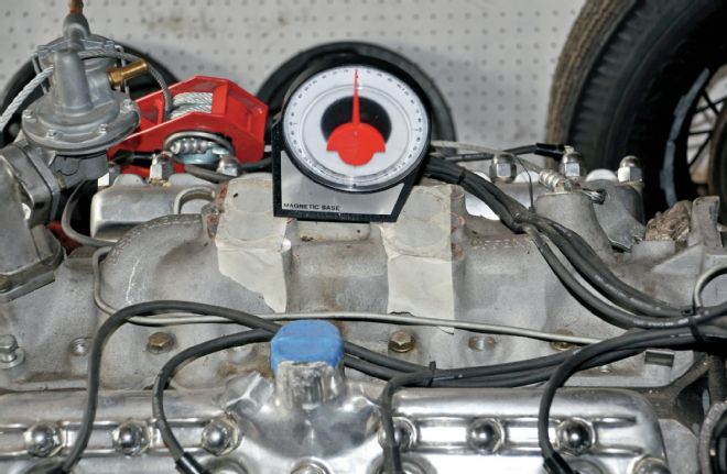
20. With the engine and trans suspended in place, an angle finder was used on the flat surface of the intake manifold to ensure it was mounted 2-3 degrees positive, the angle matching that of the pinion, to ensure perfect driveshaft operation. Normally the engine would be negative and the pinion positive, but with the engine mounted so high in this chassis the angles were reversed.
21. The finished engine mount towers, fabricated from 3⁄16-inch plate welded in place.
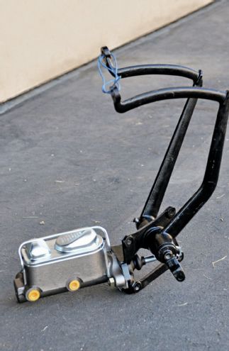
22. The pedals are replica '39 Ford from Bob Drake, with a bolt pattern for both stock Ford and later dual Mustang master cylinder.
23. The trans mount was fabricated next, along with a loop to tie the crossmember together.
24. Fjastad Jr. removed the framehorns with a Sawzall in line with the front of the center of the crossmember, then boxed the open areas.
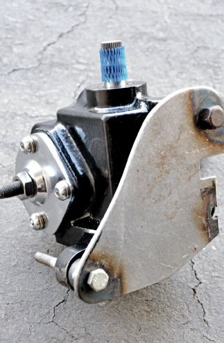
25. This aftermarket Vega steering box mount was modified by Fjastad Jr. using a bandsaw...
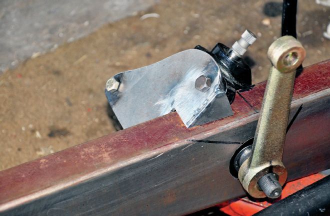
26. ...then mocked in place and a gusset added.
27. Another gusset makes everything strong. The Pitman arm locates through the framerail, as does the third mounting bolt into the upside down Vega 'box.
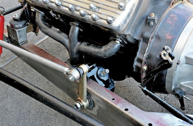
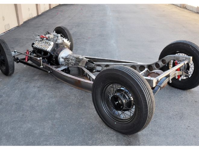
28. With the headers on the Flathead it's apparent there is plenty of space around the steering box. Because of the low chassis, we needed the Pitman arm to mount upward, and by flipping the Vega 'box we achieved this.
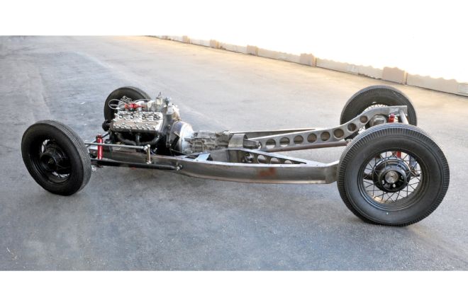
29. The rolling chassis uses 16x4-inch '35 Ford wheels with Coker/Excelsior 5.50x16 tires in the front and a set of Mike Curtis-widened 17-inch '34 Ford rims for the rear with Coker/Firestone 6.50x17 tires.