With the initial growth of our hobby came an entirely new industry offering products that made classic pickups easier to build, more comfortable to drive, and safer, too. When Ed Moss, founder of Total Cost Involved Engineering, introduced a reproduction Model A frame in 1974 it was not only revolutionary, it was the beginning of a long line of quality products for the hot rod and eventually classic truck hobbies.
Unquestionably one of the most popular suspension components to appear on the scene was the Pinto/Mustang II front suspension kit. When they were first introduced, many in the hobby were skeptical. How could a suspension from a subcompact car be up to the rigors of classic pickup use? It didn't take long for that question to be answered. The Ford frontend had stout spindles with wheel bearings that were larger than the Nova clips that were being installed at the time. Even with the demise of the Pinto, Mustang II components were readily available, installation kits were affordable, and the rack-and-pinion steering simplified installations. Most importantly it was an independent front suspension system that worked extremely well.
Like most items that have come to the hot rod/classic truck market, a variety of improvements were made in Mustang II IFS kits over the years. Larger disc brakes became available, tubular upper A-arms, and full lower A-frame kits that eliminated the strut rods (and the problems associated with their frame brackets cracking and breaking off when improperly welded) were introduced. Then, as original parts became scarce, the manufacturers stepped up and reproduced everything needed, including spindles and rack-and-pinion steering in both manual and power configurations. Today there's no need to search for original parts as these frontends come as complete assemblies and are made entirely from aftermarket components.
While there were a number of aftermarket improvements made to the original frontend's design, there was one undesirable element that often remained – the method of adjusting caster and camber. Slots in the upper mounting plates allowed the top A-frame shafts to be moved to facilitate alignment. Unfortunately, the T-bolts securing the shafts could slip, especially on nicely painted or powdercoated frames. One pothole can knock the frontend out of alignment – and if you drive your truck you'll no doubt find potholes and other obstacles that seem to have been placed as a result of an alignment shop conspiracy.
Not long ago Sal Solorzano, general manager and vice president of TCI Engineering, decided it was time to introduce a new coil spring IFS that had all of the pluses of earlier designs, but none of the minuses. The first thing the engineering staff addressed was the method of alignment – the spring towers were redesigned by doing away with the commonly used adjustment slots and adding vertical plates to serve as attachment points for the upper A-frame shafts. When the frontend is aligned, shims are sandwiched between the shafts and plates, eliminating the possibility of the adjustment slipping.
TCI Engineering has made changes in other areas as well. The suspension geometry has been revised to enhance handling and the lower control arm mounts have been redesigned and now have a 1¼-inch pin running through the crossmember for increased strength and durability. The upper and lower control use Energy Suspension urethane bushings and are said to be the strongest on the market. To further increase safety and longevity, only American-made screw-in upper and lower ball joints are used with pull-out ratings of 28,000 and 32,000 pounds, respectively.
In order to tailor their IFS to individual customer needs, there are a number of options. Classic truckers can choose stock or drop spindles, disc brakes with Ford or Chevy bolt patterns, coil springs with specially designed shock with more travel than OEM designs, or coilovers, to name a few.
TCI Engineering has taken a good thing a made it better by taking the best parts of a proven design and applying their experience and engineering expertise to eliminate its shortcomings. The result is independent front suspension redefined. Take a look and see if you don't agree.
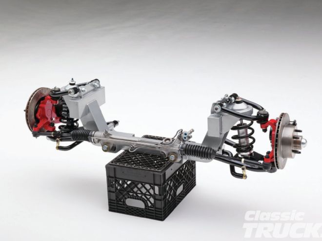
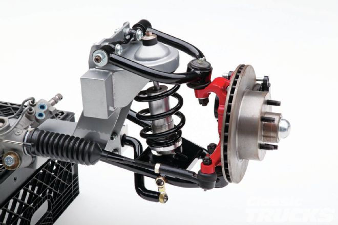
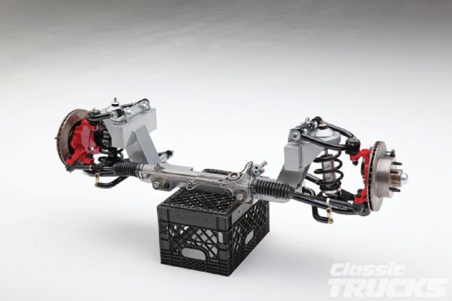 1. Total Cost Involved Engineering recently introduced their new coil spring independent front suspension with a long list of improvements over previous designs. Included are a new standard or power rack-and-pinion steering gear and a lifetime warranty on all TCI Engineering-manufactured parts.
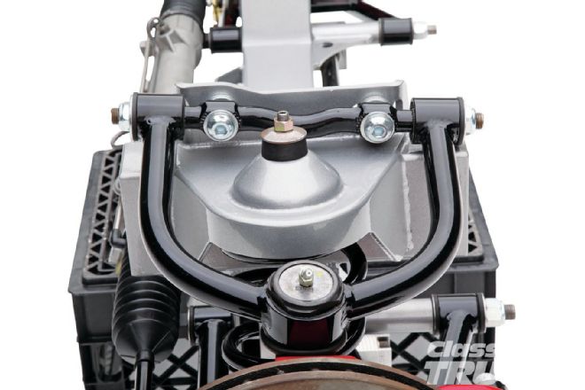 2. TCI Engineering's IFS uses shims to adjust camber, rather than slots in the upper spring plate. Upper A-arms are made from 1-inch od DOM (drawn over mandrel) tubing.
 3. Slots in the vertical plates allow for caster adjustments, but can't slip like horizontal slots can. The upper shaft is angled to provide the proper antidive characteristics during braking.
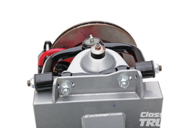
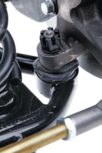
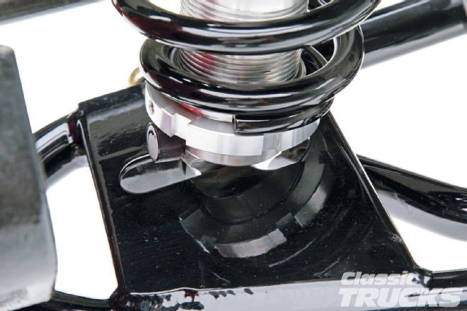
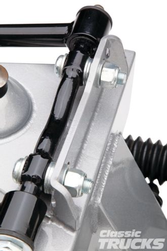 4. Here the alignment shims can be seen between the upper shaft and mounting.
 5. For comparison's sake here is the usual slotted upper hat method of adjusting caster and camber on an aftermarket IFS.
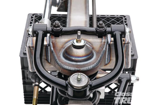
 6. Two styles of upper A-frame mounts are used. For those applications with the space, the gusseted bracket is used; for those that don't have the space for gussets, heavier material is used to provide the strength necessary.
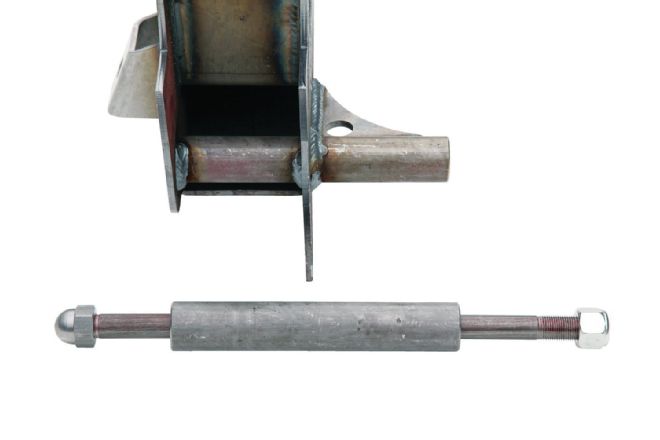 7. For maximum strength, the lower A-frame mount is one piece of 11⁄4 inch steel welded and gusseted to the 3⁄16-inch steel crossmember. Only American-made steel is used in all the components.
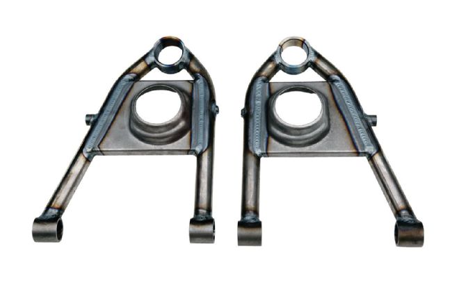 8. TCI Engineering's beefy lower A-frames are TIG-welded 11⁄8 inch DOM tubing. The ball joint sockets are installed at an 11-degree angle for more wheel travel without binding and the spring pockets are stamped to index the coils and position them at the proper angle.
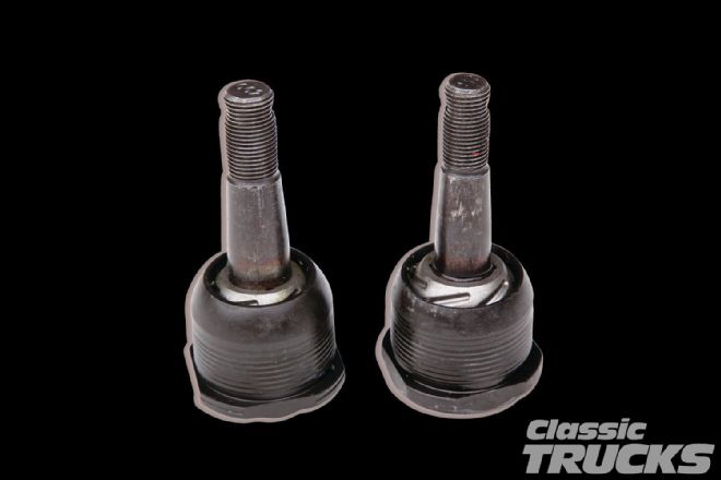 9. Heavy-duty Moog ball joints are used top and bottom. Note the differences in the lower (left) and upper (right) ball joints. The ball portion of the lower (part number Moog 719) is captured more completely to withstand the loads applied to it.
 10. The ball joint attachment holes of the TCI Engineering spindles are tapered to accept the larger pins of the lower ball joint.
 11. Spindles use a 4140 steel wheel bearing pin and are available with stock dimensions or dropped 2 inches. Frontends come with wheel bearings packed with grease and assembled rotors installed on the spindles.
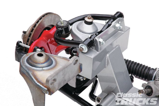
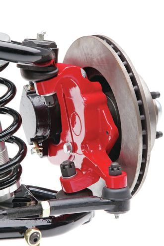
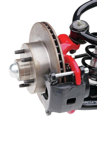 12. Brake kits include new big-bore calipers with the choice of 11-inch rotors with a Ford pattern or 101⁄2 inch with the Chevy pattern.
 13. Optional are TCI Engineering's coilover retrofit kit. A variety of other options are available, including air springs, bigger brakes, and powdercoated components.
 14. TCI Engineering's coilovers feature an adjustable collar to set spring preload as well as shock damping adjustments.
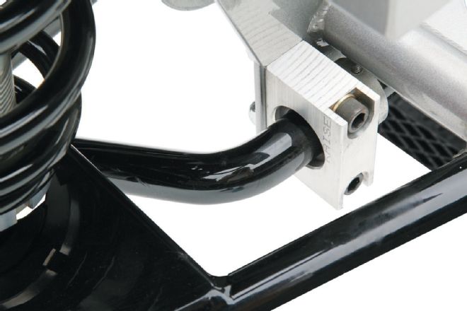 15. To reduce body roll and provide surefooted corner, Sway-A-Way antiroll bars are part of the suspension packaged. They attach to the crossmember via aluminum pillow blocks equipped with polyurethane bushings.
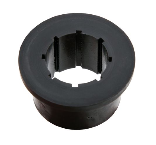 16. Energy Suspension polyurethane bushings are used exclusively throughout. Anti-squeak and corrosion preventive is applied during installation.
 17. Several antiroll bar diameters are offered. The original 3⁄4-inch bar has been disconnected – passenger car frontends now come standard with a 7⁄8-inch bar, trucks with a 1-inch. All bars attach to the control arms with adjustable Heim joints.