We have talked about alignment and related issues throughout the past 10 years with a certain regularity. It's a very important part of the total setup package that you need to attain in order to win. Lately though, because of the rush toward soft front springs combined with, not big, but smaller front sway bars and stiffer rear springs, our range of motion in the entire suspension, front and rear has changed.
Because of those changes, if a team has not addressed their alignment and checked within the new range of motion, the picture might just be very different indeed. That is because most of our suspension components travel in arcs and that make their motion non-linear. As such, we can only be correct, or know what is truly happening if we check our alignment within the range of motion that the car will actually be experiencing.
Top teams and many manufacturers of race cars have discovered the importance of alignment. There is a long history of how alignment was established by the car builders and how that might have facilitated setup trends. There was even some manipulation of the chassis alignment to attempt to cure handling ills. Those days are mostly gone now and there is good information and many different tools available to use to establish proper alignment.
 Alignment is made easier today by the use of laser systems and specialized equipment.
Of all of the setup parameters, including moment center location and setup balance, alignment ranks at the very beginning of the list. Why? Because when your alignment is not what it should be, nothing will compensate for it. The alignment package has a tremendous influence on the way a race car handles.
Along with the knowledge of the importance of alignment has come better equipment that we can use to check and adjust our race car so that it is aligned perfectly. The reason for the onslaught of interest in this issue is because car builders have finally bought into the importance of roll centers, setup balance, Ackermann issues, and alignment.
The manufacturers of race car parts have now included in their inventory tools that help us align our race cars more accurately and quickly. We now have available laser alignment systems and bolt on tools to facilitate our measuring processes.
The Elements of Proper Alignment
A. Toe Settings—We need to set the proper toe at the front and the rear. A set of tires that are not toed correctly will create a lot of drag, much like applying the brakes and sometimes more efficiently than the actual brakes. The standard of the circle track industry is to toe the front out 1/16- to 1/8-inch for asphalt cars and more, up to 1/2-inch, for dirt cars. The rear wheels are to be straight ahead and parallel to each other, having no toe at all.
B. Bumpsteer—Bumpsteer can alter the front wheel alignment due to incorrect angles in the tie rods or other factors. We need to check the bumpsteer characteristics for our front suspension at the range of travel we will experience going through the turns.
C. Front to Rear Tracking—The tire contact patches must track straight ahead from front to rear and, in most cases we need to line up the right side tire contact patches. Our final alignment will show the right side patches are in line with one another with the rearend being perpendicular to that line.
D. Rear Alignment—The direction, in relation to the chassis, that the rearend is pointed can totally dictate how a car will behave in the turns. For example, on turn entry, if the rearend is pointed to the right of the chassis centerline, no amount of setup tuning will prevent the car from being loose. That looseness will stay with the car throughout the turns, especially ruining the turn exit. If the rearend is pointed to the left of the centerline of the chassis, the car will be tight through the middle and off the corner.
There should never be any reason to misalign the rearend. It should always be very close to perpendicular to the centerline of the chassis and to the right side tire contact patches, which are themselves inline.
E. Ackermann—The last alignment priority, and one of the most important, is making sure you have very little Ackermann, which is the creation of additional front toe as the wheels are turned. On most 1/4- to 1/2-mile racetracks, we need very little Ackermann to make sure the wheels are tracking inline with the radius of the turn for each wheel.
Calculations show that for circle tracks with fairly large radii (much more than was used to design for our passenger cars for turning the corner at the stop sign) a very small amount of added toe is needed to properly align the front wheels to their individual radii.
Steps to Take in Aligning the Car
There used to be only one reliable way to align a race car and that was by using a string and either measuring to the tires at hub height or at the floor by creating right triangles on the floor to measure from. That is still a viable way to do it and necessary for the lower budget race teams.
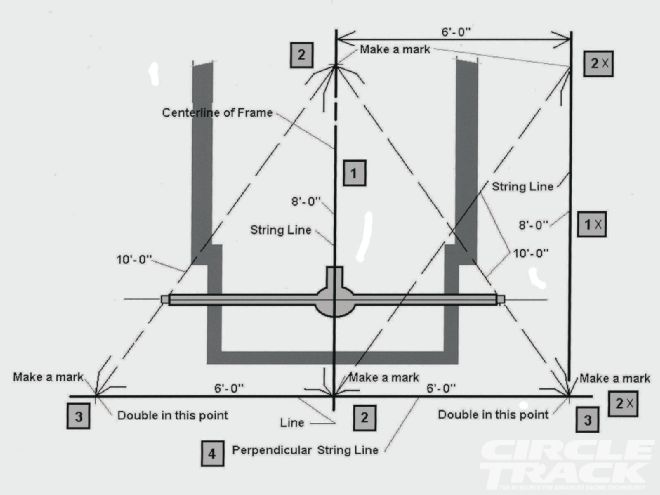 These represent the basic steps you take to setup for a string alignment. These lines will be marked on the floor and I use chalk string to snap the lines directly on the floor. 1) is establishment of the centerline, 2) is measuring for two points 8 feet apart, 2X) is establishing a parallel line outside the left side of the car at exactly 6 feet, 3) is establishing the rearend alignment points using a 6-8-10 triangle that will be perpendicular to the centerline, and 4) is snapping a chalk line or stretching a string over the #3 points.
A quicker and more accurate way to align the car in all areas is by the use of a laser system. The key to maintaining accuracy in a laser system is to be able to check the tool to make sure the beam is truly tracking at right angles to, or inline with the mounting device. All of these systems allow for checking the accuracy of the laser beams. This must be done each and every time we use the tool to check alignment.
Step 1. Race Car Attitude
Note: It's important that you consider the attitude of the car as it will be on the racetrack. With the newer setups on both asphalt and dirt, the front ends are very compressed and lower. This may change many alignment parameters that may be fine at ride height. We don't race at ride height, so placing the car at the racing attitude makes perfect sense.
When considering the following procedures please take into account your cars attitude on the racetrack and introduce the proper heights before doing any alignment work. The results will more closely match the on-track alignment if you do.
This means that instead of setting the car at normal static ride height, you lower the front end to where it will be when the car is racing on the track. Measuring within the range of motion the car will be working in is the most accurate way to do this. It matters not what the alignment is when the car is sitting in the pits if it immediately assumes a different attitude leaving the pits and all through the laps to follow.
Step 2. Bumpsteer
Before you begin your alignment setup and checks, you need to check and correct for any bumpsteer problems. If the car is going to be raced at a low attitude in the front, position the wheels in the range of motion the car will be running at on the racetrack. A perfect bumpsteer setup at static ride height might be much different when measured at high compression of the front end.
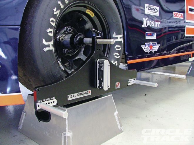
 Several companies now produce and sell alignment equipment that is portable and easy to use. This fixture combines bumpsteer measurement with wheel alignment.
Step 3. Ackermann Measurement
Let's go ahead and check our Ackermann first so that we don't upset the later adjustments and settings. This is best done accurately with the laser systems. However, the "analog" method using strings and can also tell us whether we have unwanted Ackermann or not.
If using a laser system, follow the manufacturer's suggestions and recommendations for measuring for Ackermann. If you do not have a laser system, you can use strings. Here is how you do it.
Start by pointing the front wheels straight ahead. Pull a string along the outside of the tires at the tire bulge at about the spindle pin height (avoid the lettering areas). Project the line out to the front of the car 10 feet and make a mark on the floor with the string aligned with the sidewall (I use a piece of wide masking tape and a Sharpie marker). Do this for each front tire.
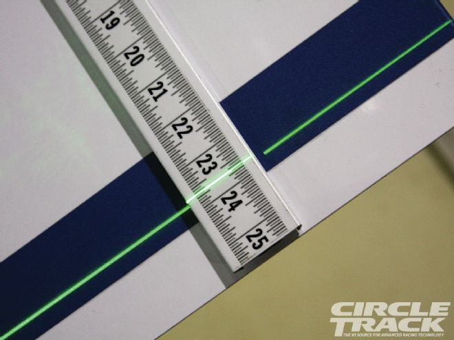
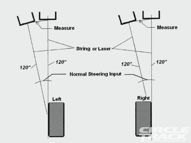 Ackermann is when we gain toe as the wheels are turned. This simple method can utilize either strings or lasers. We mark the alignment of the wheels at straight ahead first and then with the wheels turned. The distance between marks made at 10 feet in front of the hubs tells us if we have unwanted Ackermann.
Then, turn the steering wheel about the same amount it is turned on the track when you're going through the turns. Again, string the front tires and make marks at 10 feet out in front. The distance between the two marks for each wheel should be the same for the left front wheel and the right front wheel if there is no Ackermann present. If those distances are different, there is some amount of Ackermann or Reverse Ackermann present.
A greater measurement for the left tire indicates Ackermann (gain in toe-out) and a greater measurement for the right tire indicates Reverse Ackermann (loss of toe-out). A 1-inch difference equals about a 1/4-inch of Ackermann or added/loss of toe for an 85 inch circumference tire. So, if you can get your differences to 1/4-inch or less, where the left side is more, you should be good to go.
Step 4. Wheel Run-out Check
Check both the front wheels and the rear wheels for Run-out. This means that as the wheel rotates, the outer edge of the tire will wobble slightly. We must compensate for this slight distortion by finding the extreme high spot at a point equal in height to the hub height. We can simply use a jackstand to hold the tape steady and rotate the tire noting the distance from the stand. Once we locate the high point (seen as the least distance to the offset), we mark it with an arrow and then rotate the tire (be it front or rear) so the arrow is at the top pointing straight up.
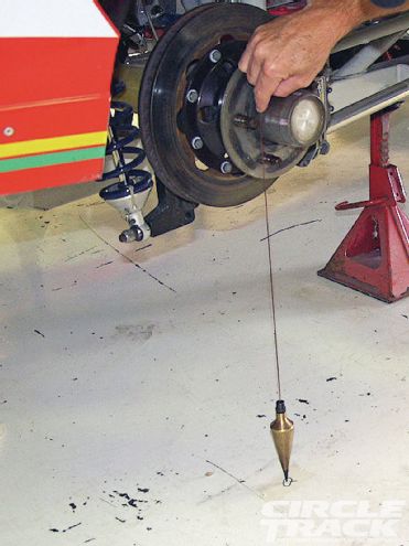 You will need a tried and true plumb bob when you setup for alignment checking as well as wide masking tape to cover the floor to mark on.
Now, check the toe at the rearend. Use toe plates or toe bars for the "analog" method and the laser systems for a more accurate assessment. Even small amounts of toe-in or toe-out are not acceptable. Be careful how each person holds the toe plates so that the measurements are consistent. Do the measurement several times to ensure accuracy and repeatability.
When using the laser systems that attach to the hubs, remember to thoroughly clean the surface of the hub and make sure there are no protruding threads from the bolt holes. It is recommended that you go over the hub surface with a flat file to eliminate any bulges or protruding edges of metal that would cause the laser to not be aligned properly.
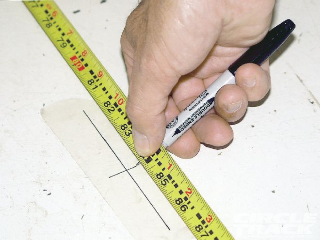 I use a thin tip magic marker and place my measurement points on masking tape that is easily removed after I’m done. Be precise in both your measurement and when marking the tape.
Follow the manufacturer's recommendations for setting up the laser systems. Remember that the accuracy of the measurements is directly related to how closely you follow the directions and how carefully you read the system. There is a logical progression to alignment and each company has put a lot of thought into the methods. The end results, if properly applied, will be the same.
Step 5. System to Frame Setup
Once the rear wheels have been toed straight ahead, square the laser system to the frame. Most car builders will align at least one framerail parallel to the intended centerline of the chassis. It may be located on the right side or as the weight box on the left side next to the driver. You can also align the laser system to the centers between the front and rear clip rails closest to the main framerails.
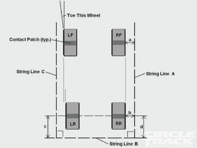 This is what our basic alignment will look like. Measurements (a) and (b) will be the same and (c) and (d) will be the same. The left side measurements will usually not be the same.
For the analog method, this setup can also be done using strings. We will setup a "box" with strings on each side and at the front and rear. We use plumb bobs to make marks on the floor off the outsides of the framerails or the front and rear clip rails. For Perimeter cars, or ones with no offset in the chassis, we can split the measurement between the front and rear clip rails closest to the center section to find the centerline of the chassis.
For offset chassis, we will be able to use a straight rail, or we could again split the clip rails. Measuring between the marks, we can split the distance in half and place a mark at the halfway point, or at the centerline of the car.
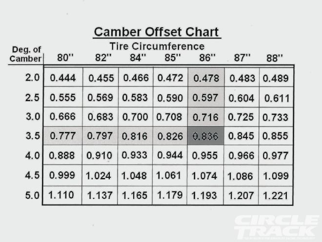 This chart will help you determine the offset of the contact patch from the position at hub height. If you string or use a laser at the hub height, then the contact patch will be some distance different when measuring to the wheel or side of the tire at hub height.
Step 6. Center the Steering Box
Center the front steering rack. This is done by turning the steering wheel lock to lock and back half the number of turns from full lock in either direction. Once mid-rack (or mid-box with drag link steering) is found, lock the steering shaft with two vise-grip type of pliers against the frame.
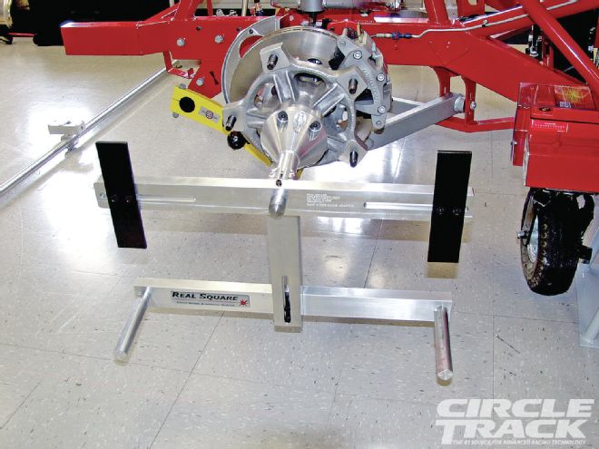
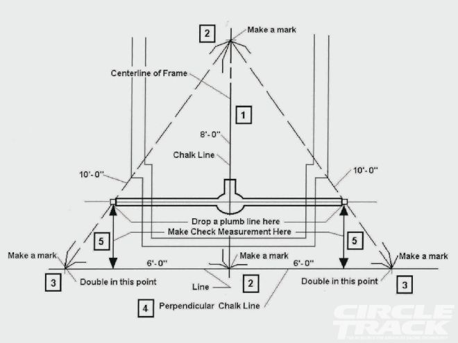 This is another view that shows the steps to take in checking the alignment of the rearend. Rearend alignment is of critical importance.
We want to make sure the steering is centered and the wheels are pointed straight ahead. Once the steering box has been set to center, adjust each tie rod so that the right and left wheels are pointing straight ahead. With the laser systems, this is done quickly and accurately.
With the string method, run a string down each side of the car at hub height and parallel to the centerline you have established. Then, simply measure to the side walls or wheel rim of each front tire with the tape measure and make both front and rear measurements equal by adjusting the tie rod lengths. We can set our wheel toe later on after we have aligned the car.
Step 7. Right Side Tire Contact Patch Alignment
Once the front wheels have been adjusted to point straight ahead and parallel to the centerline, we need to align the right side tire contact patches. We do this by using our laser systems as described in the user manuals for each system.
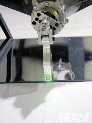
 A laser is the very best way to do your alignment because it is so accurate and easy to read. It is important that we test the laser to make sure it is pointing inline or at right angles to the body of the laser tool. A laser that points somewhere other than where it is supposed to can really mess up a race cars alignment.
Adjust the panhard or J-bar length so that the right side tire contract patches are inline, or if your desire is to offset these, set the desired amount. This means that we will either have both right side tires lined up or at least know what our offset is. For stock classes using rear suspensions that are not adjustable, you will need to run different offset wheels to achieve right side tire alignment.
When using either the string method or the lasers at hub height, we need to compensate for the camber of the wheels, which moves the tire contact patches out. At the hub height, if we line up the tire sidewalls, the RF tire contact patch will be outside that line due to the negative camber present in the RF wheel. The rear wheel may also have camber due to a cambered rearend or just the stagger.
Look at the chart to estimate how much to compensate for the cambers. Subtract the compensation amount from the offset read at the wheels to find how far from the string the wheels need to be in order to line up the right side tire contact patches.
As we adjust the rearend side to side, there is a possibility that the rearend alignment will change as the rearend moves laterally. That is why we do the right side alignment first. We will now need to check to make sure the rearend is perpendicular to the chassis centerline and if not, adjust it.
Step 8. Rearend Alignment
Once the right side tire contact patch alignment has been done, we can then square the rearend. The rear end should always be set perpendicular to the centerline of the car. We do this with the strings by creating a line that is perpendicular to the centerline we have already established. Using a simple 3-4-5 right triangle with the lengths doubled, we can measure off the centerline to establish our line to measure to the rearend.
When using the laser systems, follow the manufacturer's guidelines for doing that. The lasers will accurately measure the alignment referencing the chassis centerline.
Step 9. Setting Front Toe
The last step in the alignment process it to set the static toe at the front wheels. We can use toe plates to do this or the laser systems. Remember to be careful and accurate and do the measurements several times to be sure of the numbers. I usually just adjust the left side tie rod to set toe and leave the right side alone. You can use both if you want.
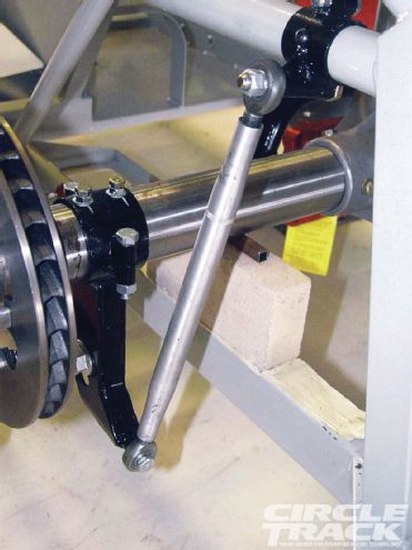 Many teams use solid links to position the rearend or front suspension control arms at the attitude that the car will be running on the track. This may be much different than the attitude the car is at in the pits at rest. We need to take into consideration the movement of the suspension and position the components will be at when on the track at speed.
Roll the car forward and back about 5 feet and recheck the toe setting. As the car settles, the overall measurements may change, but the differences should remain the same. Remember that for toe-out, the front measurement will always be more than the rear measurement on the toe plates. If you are using a string or laser to check your toe-out, the opposite is true. The front measurement from the laser/string would be less than the rear measurement. I know one crew chief/car owner that got this backwards too many times.
Step 10. Drive Line Alignment
An additional step you might consider is to align the drive line components. This means the transmission tail shaft—to driveshaft—to pinion shaft angles. The driveshaft needs some angle in relation to the tranny and pinion in order to load and rotate the needle bearings in the universal joints, but this angle can be small, at 1 to 2 degrees.
Also, the angles at each end of the driveshaft need to be equal and opposite. This provides good harmonics and if this is out of range, serious vibrations and failure of components can result.
Also remember that some cars are constructed so that from a top view, there is miss-alignment between the transmission and the pinion, especially for offset chassis. If this is enough to provide the equal and opposite angles we need, then the side view angles can be zero. The tranny, driveshaft and pinion can therefore be inline.
Conclusion
This whole process of aligning your car should only take about an hour or two if there are several team members helping. That is very little effort expended to make sure your car will track correctly and that misalignment will not interfere with your car's performance. Even if the process took a whole day, your performance improvement will make the time spent well worthwhile.
 There are even systems out there that help you measure your driveshaft alignment laterally. If you have sufficient lateral miss-alignment, you don’t need and angle from a side view and the transmission, driveshaft and pinion can be inline.
Repeat this entire process as often as you feel necessary and especially after kissing the wall or being involved in contact with another car or being involved in a crash. Maintain your intended chassis ride heights once you have performed the chassis alignment process. Once you are convinced that your car is aligned, you can then concentrate on the other important aspects of your chassis setup.