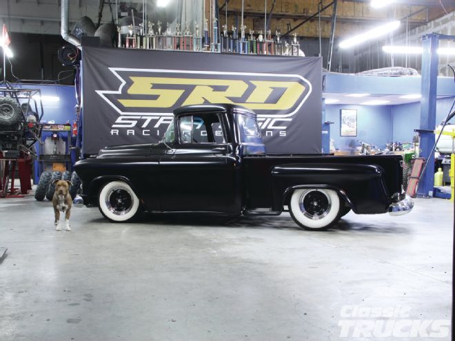
You know it when you see it – some trucks are just plain ol' cool! In this case, we explore what it takes to make a classic hot rod truck handle a little better, but more importantly, not ride like a bulldozer. To diagnose the bad road manners we have to look at the truck itself. It's a 1955 Chevy truck with the typical IFS frontend that rides OK, but as you read further you will know why.
The frontend, believe it or not, reacts to the rear suspension especially when the rear suspension is too stiff or has little to no travel. Case in point is the 1955 Chevy we tested. As we went around a normal corner, the frontend would show signs of bumpsteer and react really strange at times; bias-ply tires didn't help.
The owner Matt Colvin couldn't pinpoint why the truck didn't ride as nice as he liked, so he drove the truck over to a friend's shop to check it out. Matt ended up taking his pride and joy to Strategic Racing Designs of Vista, California, to take a look at the truck. SRD is a fabrication shop that specializes in off-road race trucks, buggies, and hot rods.
One thing Justin Herrmann, owner of SRD, noticed was the lack in travel the rear suspension had. The truck had a total of 3 inches of travel in the rear, 1 inch upward and the rest was down travel. What the lack of travel told Justin and Matt was as the truck turned or hit a bump it would bottom out the rear end. This caused the frontend to react because the rear suspension was no longer suspension. In a nutshell, the rear suspension showed its ugly head when Matt put any kind of weight in the truck, thus giving even less up travel.
So to fix the truck we could've simply installed a larger C-notch, but then Matt would still have had a stiff-riding spring rear suspension. So we took a look at RideTech's universal four-bar rear suspension kit and a set of single adjustable rear coilovers. The RideTech coilovers are the key to this installation because they make adjusting the suspension simple and have adjustment for rebound.
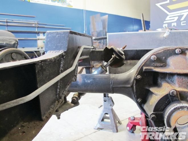
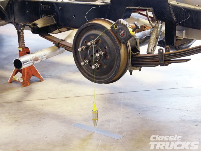
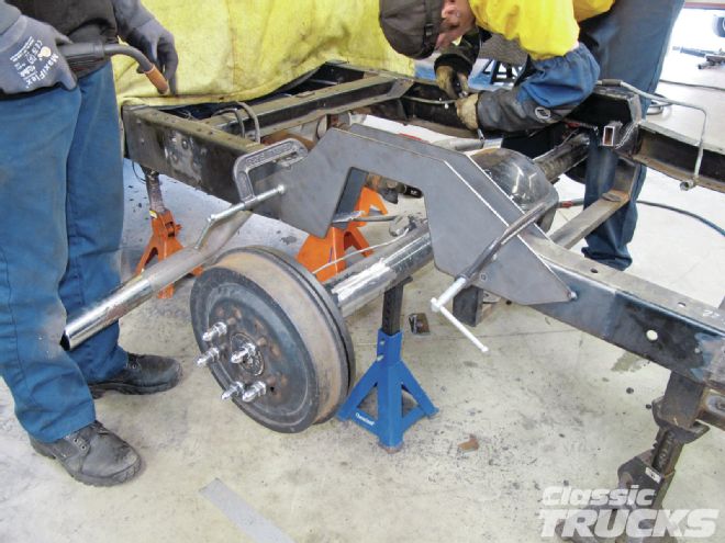
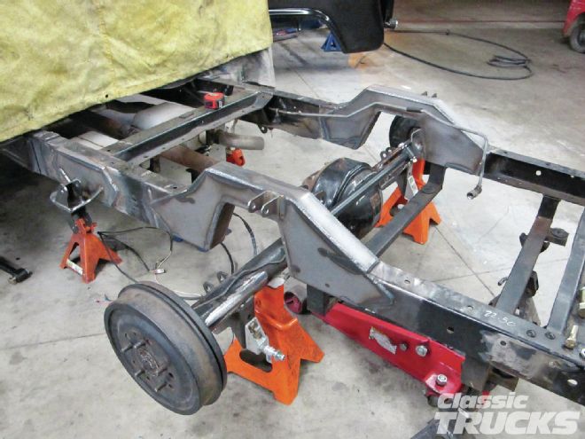
01. What you are looking at is the truck's rearend and the C-notch gap. The gap between the rear end and the C-notch is very minimal and would not allow the rear suspension to compress when hitting small bumps.
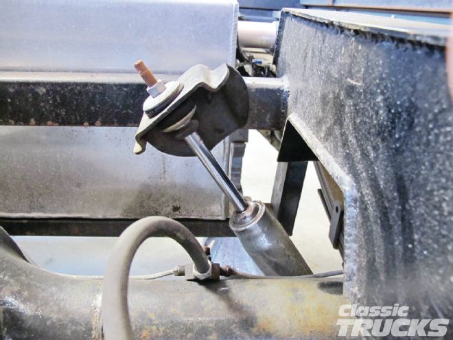
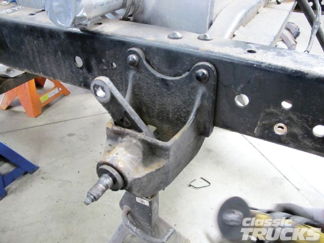
02. Here is the second issue that we ran into. The rear shocks were leaned too far in to do any dampening.
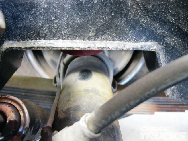
03. Now look at the shock when the suspension is compressed. Notice that the shock comes extremely close to the rear brake lines.
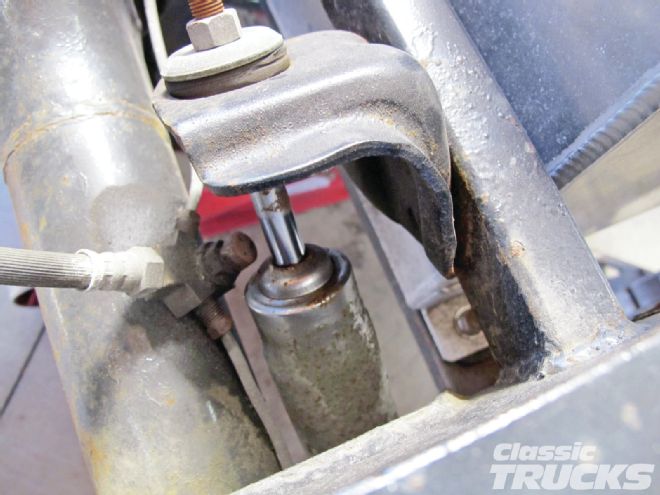
04. Here is another look at the rear shock angle with the rear suspension mid travel.
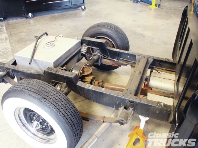
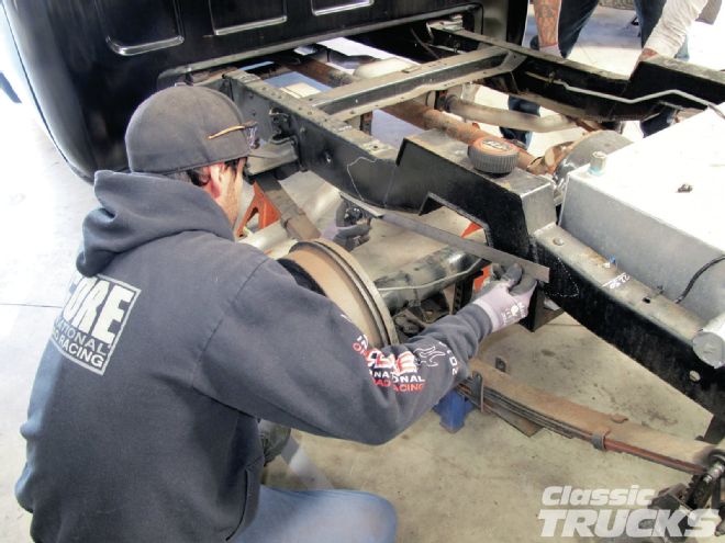
05. So the first task was to put the truck on jackstands and level the frame.
06. We removed the bed so that removing the stock spring mounts would be easier.
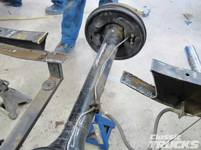
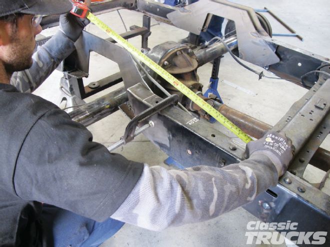
07. The rearend was measured from the cab to the center of the axle. This gives a baseline of where the axle is before the rear springs are removed.
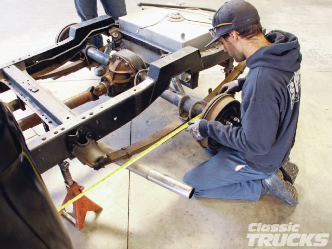
08. Justin also used a drop center and a piece of tape to mark the axle centerline on the ground. This helps when trying to center the rearend under the new RideTech four-bar setup.
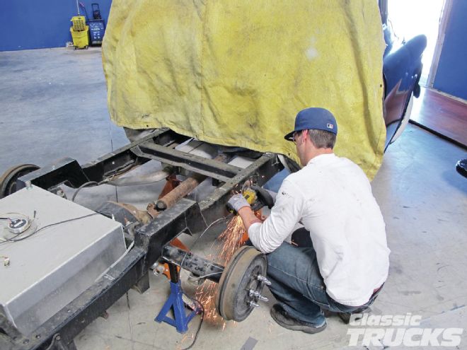
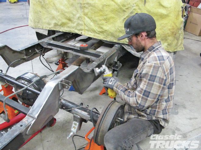
09. After the rear springs are removed we used a grinder with a cutoff wheel on the stock spring mounts. We cut off all the rivet heads and pried off the stock spring brackets.
10. Then moving to the passenger side, we cut the rest of the spring perches off.
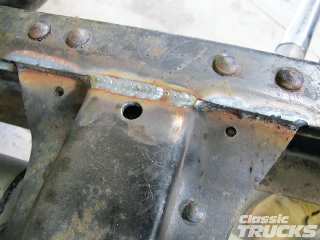
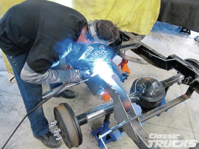
11. We welded the crossmember to the frame because we removed most of the rivets that held it in to get the spring perch off.
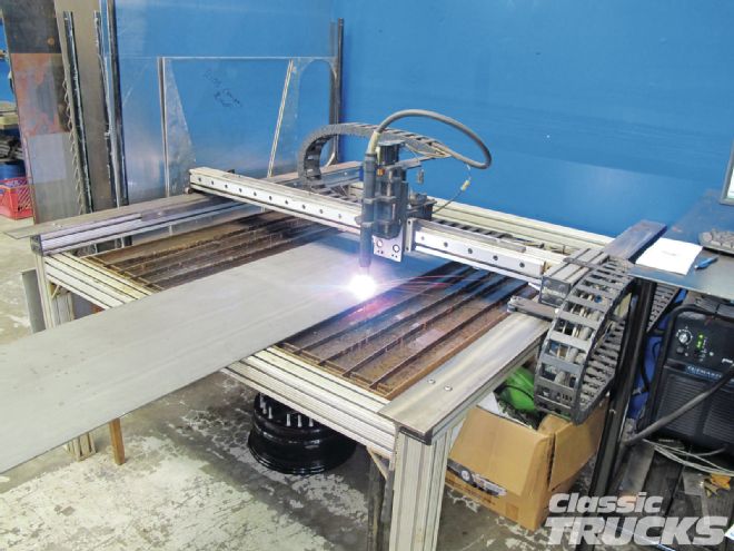
12. Justin measures the C-notch using a long-angle finder. He will then transfer the measurements to his plasma cam to make a new C-notch out of 3⁄16 plate.
13. Justin's plasma cam is a huge timesaver because it is controlled by a PC and will cut out perfect pieces every time. No grinding slag or trying to perfectly match pieces. A hand grinder, plasma cutter, or jigsaw will also work to cut out a custom C-notch.
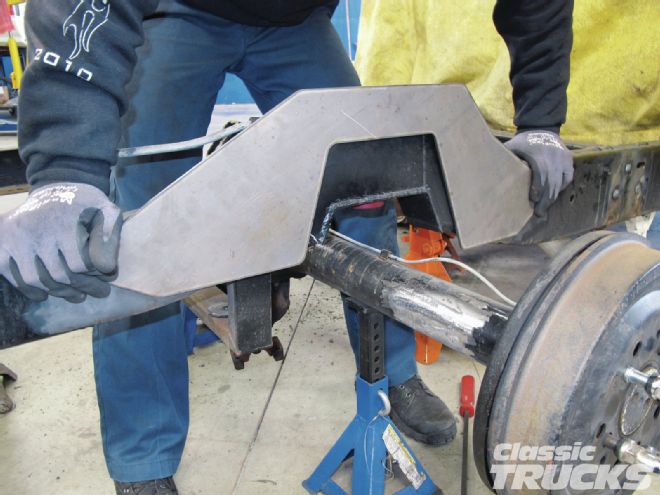
14. A quick test fit with one of the new C-notch pieces and Justin was happy with the fitment.
15. The old C-notch was cut out so that Justin could start welding in the new C-notch. We also cut off the old spring mounts on the axle housing so that the new RideTech brackets would fit.
16. As you can see we, used C-clamps to clamp the new C-notch in place. The passenger side notch was not removed until the driver side was welded into place.
17. Tacking the new C-notch in several places makes sure the frame does not shift around, while we cut out the other side.
18. Now we could measure the passenger side framerail and match it to the driver side.
19. We centered the axle with our previous marks on the ground, making sure that the frame didn't move during the construction on the new C-notch.
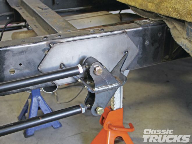
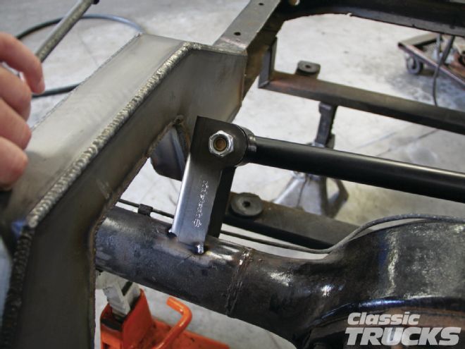
20. After centering the rear axle we went ahead and tacked one side of the RideTech four-bar assemblies on the frame and axle housing. We ran into a small problem when fitting the rear shocks in – they were pointing outward.
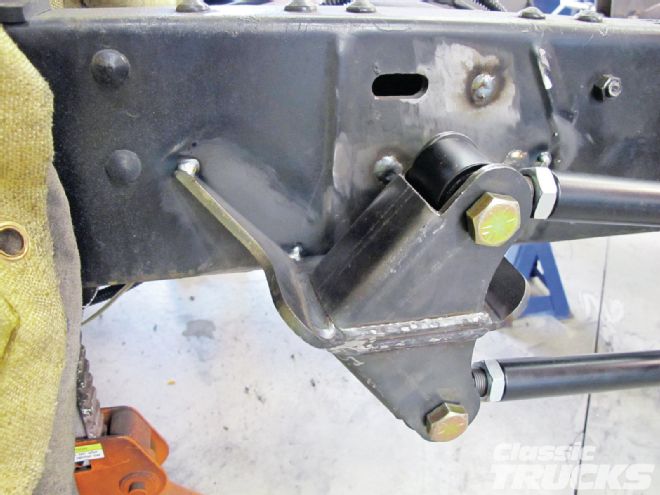
21. Our solution actually ended up making the frame look a lot nicer. We used 3⁄16 plate to space the front RideTech brackets away from the frame about a 1⁄2 inch. If you look at the frame it had bumps where the old spring perch used to be, so simply welding on the plate and spacing the RideTech bracket plate gave us plenty of room to get a better rear shock angle.
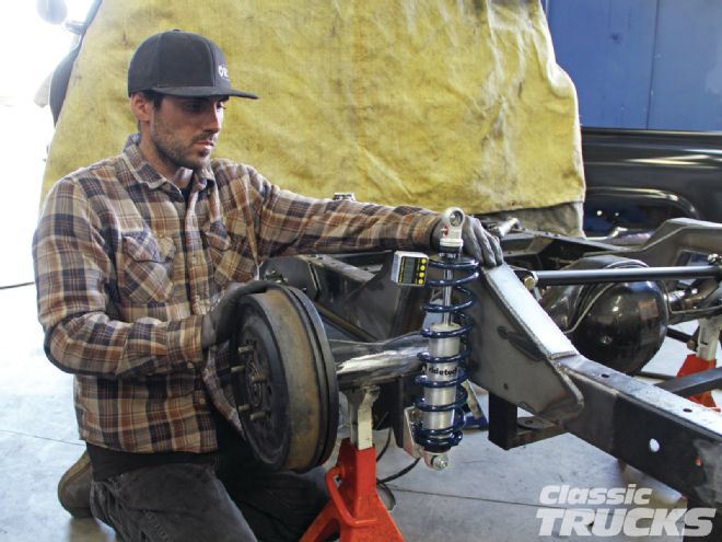
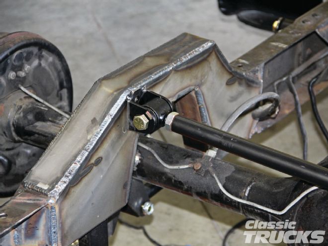
22. We wanted the top of the coilover to point inward and toward the cab. Justin set the coilovers at 5 degrees in and 5 degrees forward to make sure we had plenty of room for the coil to travel without binding on the frame.
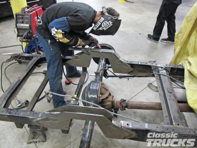
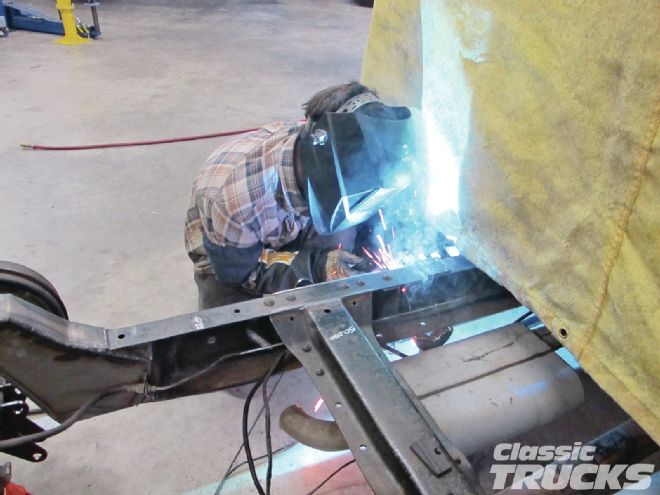
23. Once Justin was happy with how the four-bar was going in he wanted to make sure we had a solid frame to mount the coilovers and Panhard bar on. Here Justin is finish welding the C-notch onto the frame.
24. Now that the C-notch is welded in we once again used the measurement from the back of the cab to the center of the axle to give us the center point, front to rear. Next we used the drop center to give us the axle side-to-side measurement.
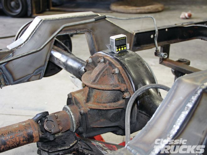
25. Pinion angle is set by placing a digital degree finder on the axle. Then we tacked the rear four-bar brackets on the housing while the vehicle was at ride height. The pinion was set to point slightly downward at -02 degrees pinion angle.
26. The Panhard bar comes long because RideTech sells the four-bar kit to fit several different applications.
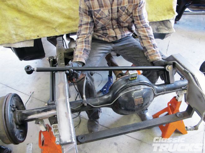
27. Justin used a chop saw to cut the Panhard bar down to size. With a 3⁄4x16 tap Justin threaded the end he cut so the adjustable rod end would screw back onto the bar.
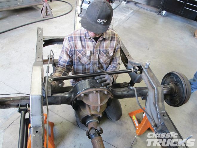
28. The lower Panhard bracket was then tacked on the rearend housing.
29. The upper Panhard bar bracket and lower Panhard bracket were located so that the Panhard was running on the same plain as the rearend. We cycled the suspension to make sure the lower Panhard bracket wouldn't hit the bed floor when it traveled up with the axle.
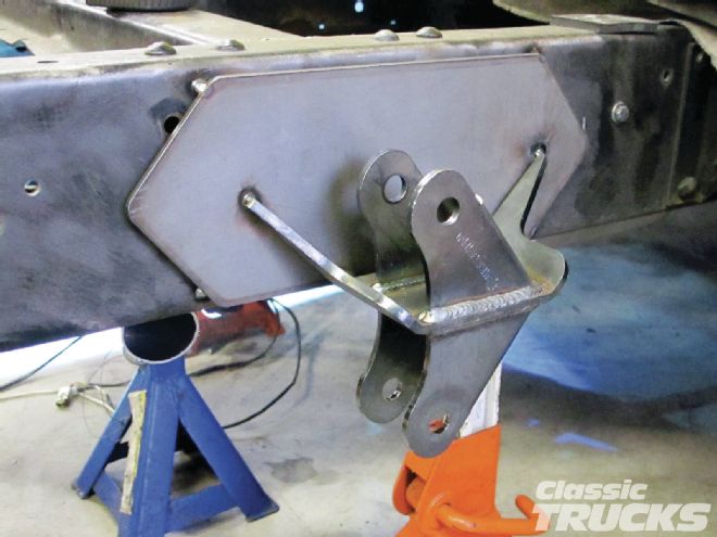
30. Some welds on tabs from an off-road store can be used to locate the upper coilover mounts.
31. We measured everything again before Justin got out the welder again. Remember now is the time to make slight changes before the four-bar is welded in solid.
32. After finish welding all the new brackets, we let it cool off for about 30 minutes. Justin and the crew of SRD did a very nice job with getting the C-notch in and RideTech four-bar nice and straight.
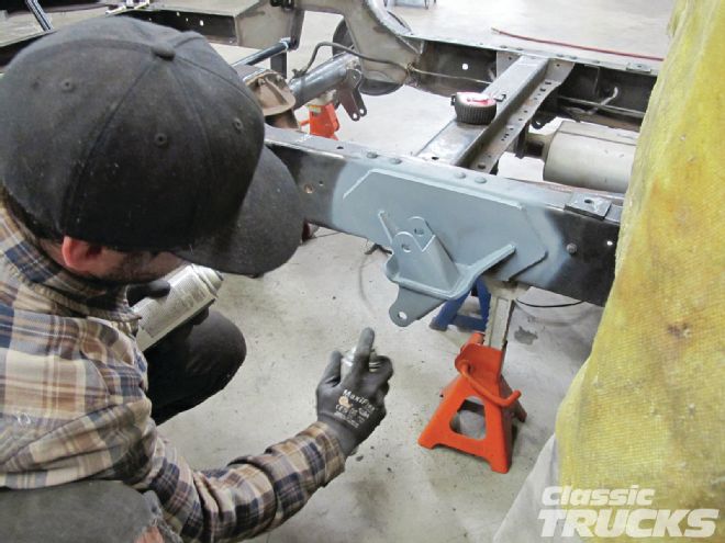
33. A quick once over with a wire wheel and the frame was ready for some primer and paint.
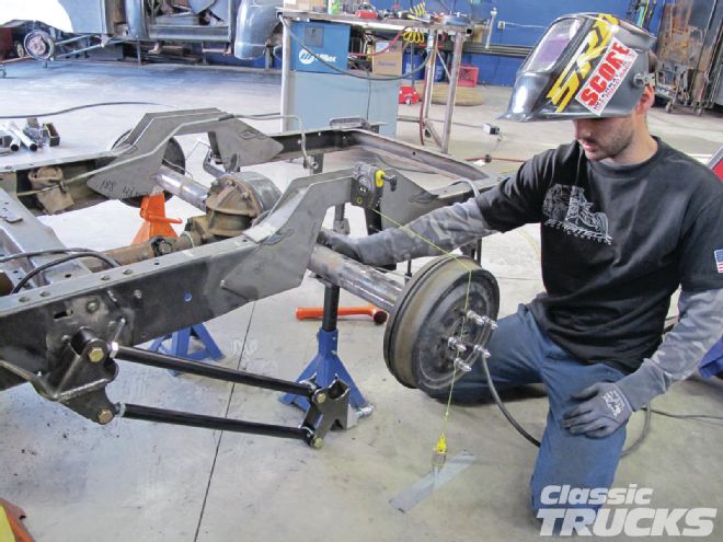
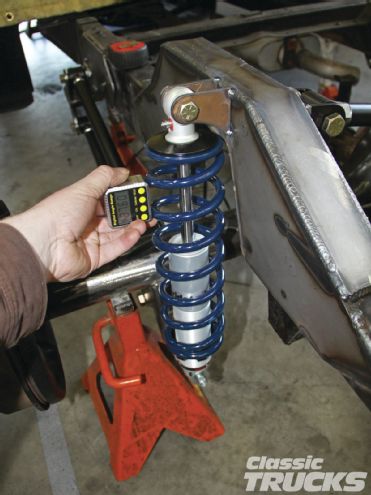
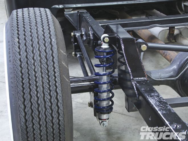
34. Now on the ground, the bars look a little off, but once the weight of the bed is placed on the frame the coilovers will compress a little more. The RideTech single adjustable coilovers can also be adjusted up or down depending on the desired ride height. The rear bars should be set up so that the bars point slightly downward toward the rearend. We end up with 5 degrees downward four-bar angle when the bed was put on and the ride height set.
35. It's hard to see in this photo, .but the shock was set up so that it was mid travel when at ride height. This means that if we have a 5-inch-stroke shock, then we set the shock up to be at mid stroke when at ride height. Setting up the shock to have upward and downward travel allows the shock to absorb the harsh bumps in the road, while still maintaining great ride quality and keep the tires on the road.
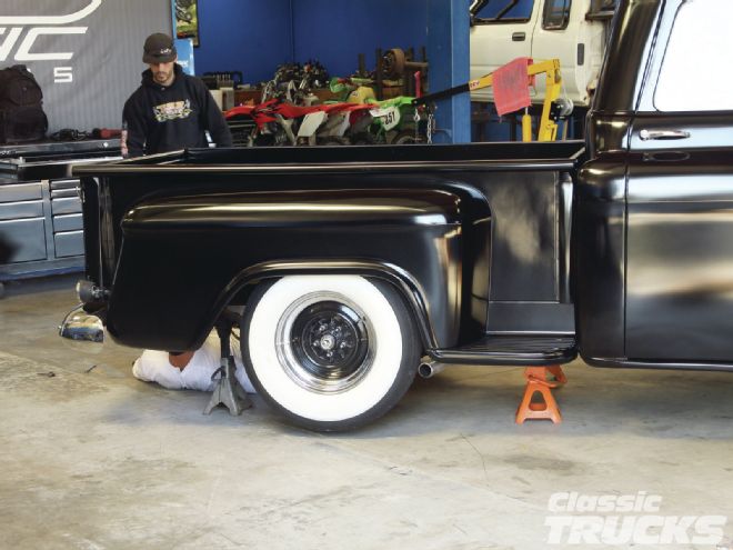
36. The bed floor is raised a few inches just to let you know.
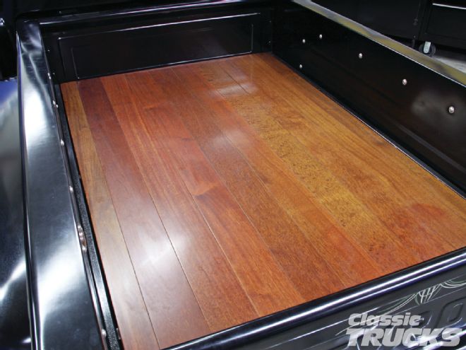
37. As you can see the truck still sits really low, but now it has tons more travel in the rear suspension. The frontend feels a lot better and the truck is much more predictable to drive down the road. No more bottoming out the rearend to the frame, and check out the nice bed floor Matt installed over the C-notch. The night we finished the install, Matt drove the truck around the block a few times. When he came back he was amazed by how well the truck drove. In his words, and I quote, "This drives like a new truck now. Why didn't I do this sooner?"