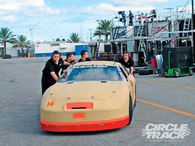
 One of the first indications of a car that has poor alignment of the four tires is that it takes a whole crew to push. Not that this is the case with this car, but most teams will say that the easier a car rolls, the better it seems to run. High rolling resistance is detrimental to peak performance and can be holding your program back.
Top teams and many manufacturers of race cars have discovered the importance of alignment. There's a long history of how alignment was established by the car builders and how that might have facilitated setup trends. There was even some manipulation of the chassis alignment to attempt to cure handling ills. Those days are mostly gone now and there's good information and many different tools available to use to establish proper alignment.
Of all of the setup parameters, including moment center location and setup balance, alignment ranks at the very beginning of the list. Why? Because when your alignment is not what it should be, nothing will compensate for it. The alignment package has a tremendous influence on the way a race car handles.
Along with the knowledge of the importance of alignment has come better equipment that we can use to check and adjust our race car so that it's aligned perfectly. The reason for the onslaught of interest in this issue is because car builders have finally bought into the importance of roll centers, setup balance, Ackermann issues, and alignment. The manufacturers of race car parts have now included in their inventory tools that help us align our race cars more accurately and quickly. We're going to show you some advanced systems available for the short-track racer.
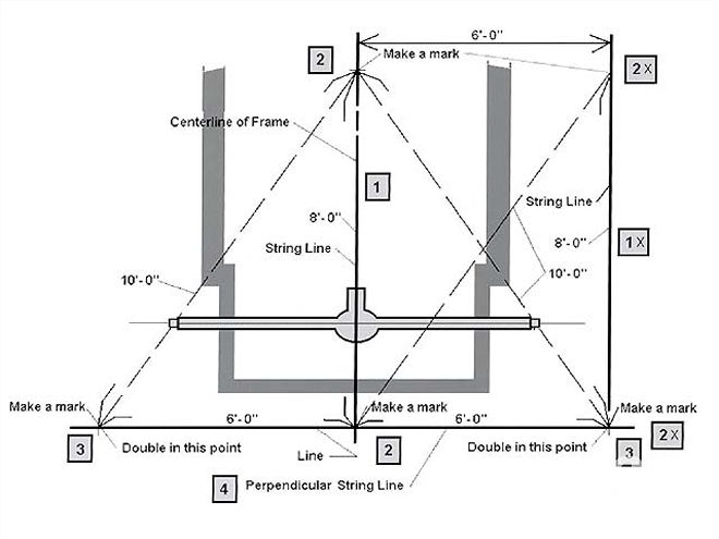 In the past it was common to string a car by making marks on the floor. This is a good method for checking rearend square and can be used to line up the right-side tires. It's a little slower to do than the raised string method but can be more accurate due to the process of dropping points down to the floor with a plumb bob and then making direct measurements to the rearend. The numbers relate to the sequence of making the lines.
The Elements of Proper AlignmentA. Toe Settings We need to set the proper toe at the front and the rear. A set of tires that isn't toed correctly will create a lot of drag, much like applying the brakes, and sometimes more efficiently than the actual brakes. The standard of the circle track industry is to toe the front out 1/16 to 1/8 inch for asphalt cars and more, up to 1/2 inch, for dirt cars. The rear wheels are tobe straight ahead and parallel to each other, having no toe at all.
B. Front-to-Rear Tracking The tire contact patches must track straight ahead from front to rear and, in most cases, we need to line up the right-side tire contact patches. Our final alignment will show the right-side patches are in line with one another with the rearend being perpendicular to that line.
C. Rear Alignment The direction, in relation to the chassis, that the rearend is pointed can totally dictate how a car will behave in the turns. For example, on turn entry, if the rearend is pointed to the right of the chassis centerline, no amount of setup tuning will prevent the car from being loose. That looseness will stay with the car throughout the turns, especially ruining the turn exit. If the rearend is pointed to the left of the centerline of the chassis, the car will be tight through the middle and off the corner.
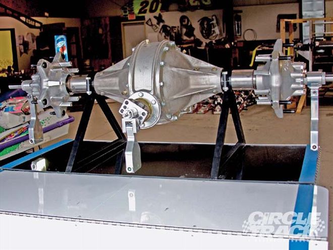 For many procedures, we would want better access to some of the components used for adjusting alignment, so removal of the wheels is necessary. When measuring with the wheels off the car, it's a common practice to use solid links in place of shocks or coilovers to position the rearend and front spindles where they would be in relation to the chassis at ride height.
There should never be any reason to misalign the rearend. It should always be perpendicular to the centerline of the chassis and to the right-side tire contact patches, which are themselves inline.
D. Ackermann Adjusted The last alignment priority, and one of the most important, is making sure you have very little Ackermann, which is the creation of additional front toe as the wheels are turned. On most - to -mile racetracks, we need very little Ackermann to make sure the wheels are tracking inline with the radius of the turn for each wheel.
Calculations show that for circle tracks with fairly large radii (much more than was used to design our passenger cars for turning the corner at the stop sign) a very small amount of added toe is needed to properly align the front wheels to their individual radii.
The three lasers in the Accu-Laser system mount at the pinion and the rear wheel hubs. The green laser light is a vertical plane and the units hang exactly vertical with bearing connectors.
Some Systems That Are Available For Measuring AlignmentThe Brunnhoelzl Accu-Laser Measurement System A more recent addition to the laser alignment array of products is the one developed by George Brunnhoelzl. His system attacks the "problem" of alignment from a little different view. This system mounts to the rearend, where we usually end up anyhow, and projects out to the chassis. The center laser mounts to the pinion, which is at a right angle to the axle tubes. This eliminates errors caused by wheel toe or bent axle tubes. The center laser projects up past the front of the chassis and can be used to align with the front crossmember, chassis front stub, and front tires.
The light is a green laser, which is brighter. All of the lasers are designed to work on a pendulum effect. That means the laser will hang straight down eliminating the effects of camber. The lasers come in battery style or rechargeable and mount in minutes.
The laser units hang vertically from the pinion and right and left hub adapters. The light that is projected is in a vertical plane where measurements may be taken from the ground or any height reached by the light. This facilitates measurements to the tire contact patch, chassis frame-rails, or crossmember.
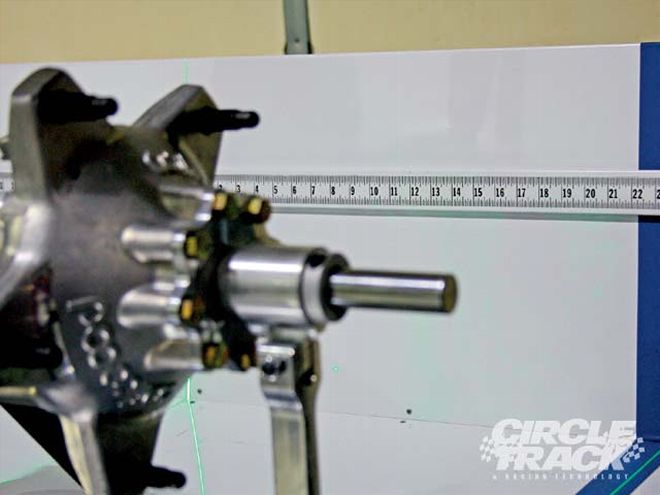 Note how bright and narrow the green laser light is for the Accu-Laser system. The pinion mount laser projects to the front of the car and helps you align the rear to the chassis centerline and/or the front wheels. This makes the process of squaring the rearend fast and accurate.
The basis of the system is the central laser attached to the pinion bearing mount. The pinion shaft is at a direct right angle to the axle line. Therefore, the projection of this line is the basis of the relationship of the rearend to the front tires and the chassis, be it a straight rail or perimeter chassis. The rearend can then be aligned to the front tire contact patches and other critical issues can be addressed such as front and rear toe bumpsteer, rear steer, and more.
The DRP Real Square Laser Wheel Alignment System The Real Square system has undergone some major improvement over the past year and now contains many features for low-tech and high-end systems. The racer can chose from several different levels of system from a simple string method to the advanced newly released RS400Pro Dual Wheel/Triple Laser Alignment System with Level. It's designed for teams with a special emphasis on dynamic measurements.
The RS400Pro system can check all alignment parameters including toe (simultaneous four wheel measurements at tire diameter), Ackermann and bump, camber (static and dynamic), caster/pinion angle (static and dynamic), lateral wheel location or track (static and dynamic and referenced to chassis centerline), align driveline (static and dynamic), measure body points, measure suspension mounting locations (referenced to chassis centerline), measure axle tubes (toe and camber).
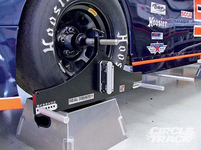 The DRP RS400Pro system provides the ability to measure many functions on the car. By using their unique fixtures, you can measure and adjust all of the critical alignment issues on a modern race car quickly and easily. This latest edition of the Real Square Laser system incorporates new techniques and functions over last year's system. This is brand-new and debuted at PRI this past December.
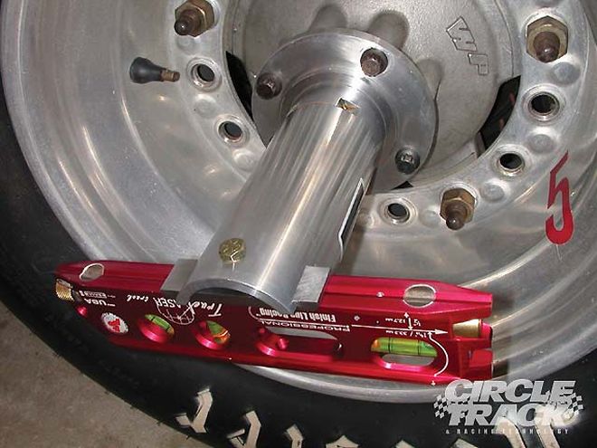
The True Laser Track System Finishline Racing manufactures the True Laser Track System which mounts directly onto the hub of the car. This system uses lasers to align the rearend to the chassis by measuring first to targets at the front and rear of the car and then to the chassis points. It can be used to set toe, Ackermann, wheel/tire alignment, rearend toe, and alignment and can be tested for accuracy before use.
The new model for 2009 uses a magnetic mount which makes it easy to remove the lasers and turn them around for accuracy checking. Another new feature is the laser's beam is now adjustable for windage and elevation for even better accuracy. Adapters are available for all hub designs.
Steps To Take In Aligning The CarThere used to be only one reliable way to align a race car and that was by using a string and either measuring to the tires at hub height or at the floor by creating right triangles on the floor to measure from. That is still a viable way to do it and necessary for the lower-budget race teams.
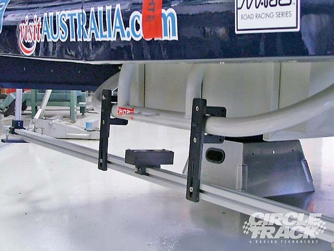 One of the new features of the Real Square Laser RS400Pro system is a bar mounted to the chassis where the laser is projected onto all four wheel brackets to independently measure alignment, camber, steer, Ackermann, and more. There are three lasers, one for each side and one at the centerline of the chassis.
A quicker and more accurate way to align the car in all areas is by the use of a laser system. The key to maintaining accuracy in a laser system is to be able to check the tool to make sure the beam is truly tracking at right angles to the mounting devise. The units we can use are the True Laser Track, the Real Square Alignment Systems, and the new entry by Brunnhoelzl. All of these systems allow for checking the accuracy of the laser beams. This must be done each and every time we use the tool to check alignment.
Step 1 Wheel Run-out Check Check both the front wheels and the rear wheels for run-out. This means that as the wheel rotates, the outer edge of the tire will wobble slightly. We must compensate for this slight distortion by finding the extreme high spot at a point equal in height to the hub height. We can simply use a jackstand to hold the tape steady and rotate the tire noting the distance from the stand. Once we locate the high point (seen as the least distance to the offset), we mark it with an arrow and then rotate the tire (be it front or rear) so the arrow is at the top pointing straight up.
Now, check the toe at the rearend. Use toe plates or toe bars for the "analog" method and the laser systems for a more accurate assessment. Even small amounts of toe-in or toe-out are not acceptable. Be careful how each person holds the toe plates so that the measurements are consistent. Do the measurement several times to ensure accuracy and repeatability.
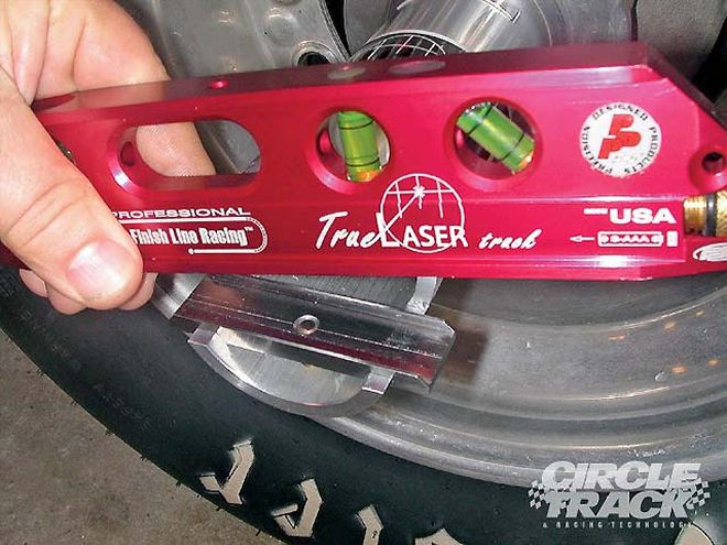 The newest version of the True Laser Track system uses magnetic mounts for attaching the laser to the hub fixture. This makes removal and reversal of the lasers quick and easy. Reversal of the lasers is one of the steps in checking the accuracy of the unit. It's very important to be able to check the alignment of the laser in relation to the laser housing. The TLT system is easily checked each time you use it. The newest units have adjusting screws for windage and elevation so that the user can correct any errors in laser line direction in relation to the housing due to mishandling mistakes.
When using the laser systems that attach to the hubs, remember to thoroughly clean the surface of the hub and make sure there are no protruding threads from the bolt holes. It's recommended that you go over the hub surface with a flat file to eliminate any bulges or protruding edges of metal that would cause the laser to not be aligned properly.
Follow the manufacturer's recommendations for setting up the laser systems. Remember that the accuracy of the measurements is directly related to how closely you follow the directions and how carefully you read the system. There's a logical progression to alignment and each company has put a lot of thought into the methods. The end results, if properly applied, will be the same.
Step 2 System-to-Frame Setup Once the rear wheels have been toed straight ahead, square the laser system to the frame. Most car builders will align at least one frame-rail parallel to the intended centerline of the chassis. It may be located on the right side or as the weight box on the left side next to the driver. You can also align the laser system to the centers between the front and rear clip rails closest to the main framerails.
For the analog method, this setup can also be done using strings. We will set up a "box" with strings on each side and at the front and rear. We use plumb bobs to make marks on the floor off the outsides of the framerails or the front and rear clip rails. For perimeter cars, or ones with no offset in the chassis, we can split the measurement between the front and rear clip rails closest to the center section to find the centerline of the chassis.
 The True Laser Track units can be rotated to point ahead or back on the car. Targets placed at the front and rear of the car are used to measure alignment.
For offset chassis, we'll be able to use a straight rail, or we could again split the clip rails. Measuring between the marks, we can split the distance in half and place a mark at the halfway point, or at the centerline of the car.
Step 3 Center the Steering BOX Center the front steering rack. This is done by turning the steering wheel lock to lock and back half the number of turns from full lock in either direction. Once mid-rack (or mid-box with drag link steering) is found, lock the steering shaft with two Vise-Grip-type of pliers against the frame.
We want to make sure the steering is centered and the wheels are pointed straight ahead. Once the steering box has been set to center, adjust each tie rod so that the right and left wheels are pointing straight ahead. With the laser systems, this is done quickly and accurately.
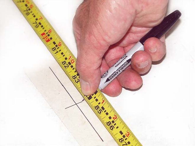 When making marks on the shop floor, you can use wide masking tape and a Sharpie fine point pen. This helps keep the floor surface clean and provides a very good surface for making lines and labeling the marks. Make sure your tape is straight and level when making these measurements. Don't concentrate so hard on the numbers that you miss that the tape is bent around a jackstand chassis support.
With the string method, run a string down each side of the car at hub height and parallel to the centerline you have established. Then, simply measure to the side walls or wheel rim of each front tire with the tape measure and make both front and rear measurements equal by adjusting the tie-rod lengths. We can set our race toe later on after we have aligned the car.
Step 4 Right-side tire contact Patch Alignment Once the front wheels have been adjusted to point straight ahead and parallel to the centerline, we need to align the right-side tire contact patches. We do this by using our laser systems as described in the user manuals for each system.
Adjust the Panhard or J-bar length so that the right-side tire contact patches are inline, or if your desire is to offset these, set the desired amount. This means that we will either have both right-side tires lined up or at least know what our offset is. For stock classes using rear suspensions that are not adjustable, you will need to run different offset wheels to achieve right side tire alignment.
When using the string method, we need to compensate for the camber of the wheels which moves the tire contact patches out. At the hub height, if we line up the tire sidewalls, the RF tire contact patch will be outside that line due to the negative camber present in the RF wheel. The rear wheel may also have camber due to a cambered rearend or just the stagger. Look at the chart to estimate how much to compensate for the cambers. Subtract the compensation amount from the offset read at the wheels to find how far from the string the wheels need to be in order to line up the right-side tire contact patches.
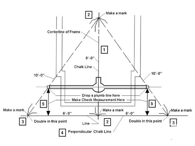 This is what we should end up with after aligning the rear to the right-side tire contact patches. Measurement points 5 should be equal. Once the rearend has been aligned perpendicular to the chassis centerline and the right-side tire contact patches lined up, we will deal with the front toe and Ackermann issues.
As we adjust the rearend side-to-side, there's a possibility that the rearend alignment will change as the rearend moves laterally. That's why we do the right-side alignment first. We'll now need to check to make sure the rearend is perpendicular to the chassis centerline and if not, adjust it.
Step 5 Rearend Alignment Once the right-side tire contact patch alignment has been done, we can then square the rearend. The rearend should always be set perpendicular to the centerline of the car. We do this with the strings by creating a line that is perpendicular to the centerline we have already established. Using a simple 3-4-5 right triangle with the lengths doubled, we can measure off the centerline to establish our line to measure to the rearend.
When using the laser systems, follow the manufacturer's guidelines for doing that. The lasers will accurately measure the alignment referencing the chassis centerline.
Step 6 Ackermann Measurement It's now time to measure for the amount of Ackermann present in the steering system. This is best done accurately with the laser systems. However, the "analog" method using strings can also tell us whether we have unwanted Ackermann or not.
If using a laser system, follow the manufacturer's suggestions and recommendations for measuring for Ackermann. If you don't have a laser system, you can use strings. Here's how you do it.
Start by pointing the front wheels straight ahead. Pull a string along the outside of the tires at the tire bulge at about the spindle-pin height (avoid the lettering areas). Project the line out to the front of the car 10 feet and make a mark on the floor with the string aligned with the sidewall (I use a piece of wide masking tape and a Sharpie marker). Do this for each front tire.
Then, turn the steering wheel about the same amount it's turned on the track when you're going through the turns. Again, string the front tires and make marks at 10 feet out in front. The distance between the two marks for each wheel should be the same for the left front wheel and the right front wheel if there is no Ackermann present. If those distances are different, there is some amount of Ackermann or Reverse Ackermann present.
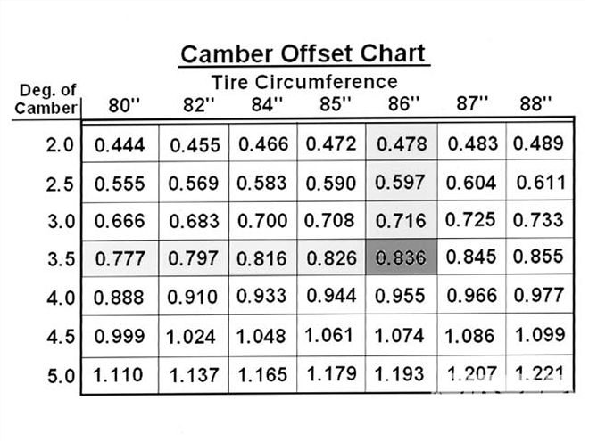 The tire contact patch is offset from the center of the wheel at hub height when we add camber to a wheel. The chart shows how far offset the contact patch center is related to the wheel center at hub height. This is important to know when stringing a car at hub height which is a common practice. If we string along the rear tire bulge to the front tire, the front tire-to-string should be a gap equal to the chart offsets. If the rear and front wheels have camber, then subtract the rear offset from the front offset and make your front tire gap that dimension.
A greater measurement for the left tire indicates Ackermann (gain in toe-out) and a greater measurement for the right tire indicates Reverse Ackermann (loss of toe-out). A 1 inch difference equals about a inch of Ackermann or added/loss of toe for an 85 inch circumference tire. So, if you can get your differences to inch or less, where the left side is more, you should be good to go. A recent car we checked had a three inch difference, or almost inch of added toe in the turns.
Step 7 Setting Front Toe The last step in the alignment process it to set the static toe at the front wheels. We can use toe plates to do this or the laser systems. Remember to be careful and accurate and do the measurements several times to be sure of the numbers. Adjust the left-side tie rod to set your toe. Leave the right side alone.
Roll the car forward and back about five feet and recheck the toe setting. As the car settles, the overall measurements may change, but the differences should remain the same. Remember that for toe-out, the front measurement will always be more than the rear measurement on the toe plates. If you are using a string or laser to check your toe-out, the opposite is true. The front measurement from the laser/string would be less than the rear measurement. I know one crew chief/car owner who got this backwards too many times.
Conclusion This whole process of aligning your car should only take about an hour or two if there are several team members helping. That's very little effort expended to make sure your car will track correctly and that misalignment will not interfere with your car's performance. Even if the process took a whole day, your performance improvement will make the time well worthwhile.
Repeat this entire process as often as you feel necessary and especially after kissing the wall or being involved in contact with another car or being involved in a crash. Maintain your intended chassis ride heights once you have performed the chassis alignment process. Once you are convinced that your car is aligned, you can then concentrate on the other important aspects of your chassis setup.