 We now have a rolling chassis almost ready for action. We have bolted on all of the various parts and set up the car. Here is how we did it. Photo by Rob Fisher
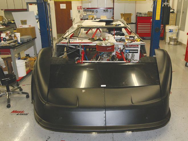
Our Dirt Late Model project car has been undergoing a lot of change over the past month. We installed most of the body, all of the suspension parts, the rearend, and the motor and transmission. Now comes the fun part. We are ready to set up the car. As promised, here is a detailed summary of what we did and why.
We looked at where we were going to be racing and how our driver likes to race and tried to apply the technology we have been presenting in CIRCLE TRACK over the past few years. Fortunately, we have really good sources within the top levels of Dirt Late Model racing circles and we know how the top teams think and the way they approach their racing. We also know how it should be done technically and the two, practical application and theory, are on the same track.
Front Geometry
The first step in any first time setup is the front end geometry settings. We have already redesigned the front moment center location from what we had. Our MC was located, after dive and roll, at about 3.70 inches off the ground and 6.10 inches left of centerline. This is the dynamic location and the static location, the one at ride height, started farther left at about 18 inches left of centerline.
To get to those locations, we needed to drill new upper mount holes and then reinforce those holes with large washers welded on both sides of the square vertical tubing. We also installed Mono-Ball ball joints in both lower arms and spaced them so that the ball joints were as low as possible to take most of the angle out of the lower arms. This controlled our movement and location of the MC.
 Before setting our front geometry, we needed to install links to simulate the position of the spindles to where they would be in relation to the chassis when the car is assembled, at ride height and with all of the weight in it.
We needed to set our caster, camber, and toe so we raised our car and installed links where the shocks mount that would simulate the spindle position at ride height with all of the weight on the car. These links can be made of any material, and we chose two strips of one-inch wide aluminum that would overlap. We clamped them with a vise grip plier and drilled a hole and bolted them together.
We decided on a caster split of 3.50 degrees positive caster for the RF and 2.50 degrees of positive caster for the LF. This provides some ease in turning left, but does not overly restrict turning the wheel to the right such as would be the case with a larger caster split.
The cambers we set were: LF = 2.50 degrees positive (top leaning out away from the centerline) and RF = 4.50 degrees negative (top leaning in towards the centerline). Because we will be setting this car up to be more balanced and using the left front tire more so than some setups, we did not need to put high amounts of camber in the RF.
We set toe with the steering rack centered and at 1/4-inch out, which we decided was plenty enough to stabilize the car. Some suggest higher amounts of toe, but we feel that those high numbers work best when the setup promotes a lot of front load transfer and the LF isn't working so hard. Once the LF is set up to stay loaded, high amounts of toe will work against being able to turn the car as the two front tires fight to go in separate directions.
Rear Geometry
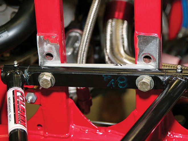
We had already made the decision to take most of the rear steer out of the car, so when we mounted the rear links on this Z-link, swing arm car, we did so with that in mind. Both the upper and lower links are more parallel to the ground and with the bird-cage connection to the rearend provides wheel travel with little or no rear steer.
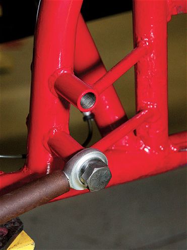
 To relocate our moment center, we needed to construct new mounting holes in our upper vertical tubing. This provided more arm angle to improve the location and migration of the MC.
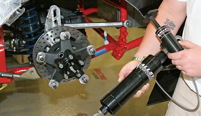
The axle wrap-up is controlled by a unique design of pull bar built by Bert that we discovered some 10 years ago and one that I like. Then we tested it at Eldora and gained 3/10 in a back to back test. The data off the sensors we had installed on the link showed that it worked to control wheel spin all of the way around the track where a simpler design became fully extended and solid soon after power was applied.
The speed of movement on return to static position, when the car is off the throttle and entering the turns, is controlled by a pair of AFCO shocks specially designed for this task. The rates are spoken as being approximately 10 percent out and 90 percent in. This means that they provide very little resistance to being extended when the car accelerates, and considerable resistance to compression to control the force of the 3,500 pound spring in the pull bar as the driver enters the turn.
We then aligned our rearend in the car. The dirt chassis are not easy to use for alignment because there isn't any real symmetry between the two sides of the "frame." So, we aligned the right side tires with the front wheels pointed straight ahead and squared the rearend to that line. Our right side tire contact patches are inline and the rearend is at ninety degrees to that.
Driveline Geometry
Another area of racecar geometry that should be evaluated when putting your car together is the driveline geometry. There is a lot to be gained in this area for both performance and reliability. We measured our relationships between the driveshaft and both the pinion and the transmission.
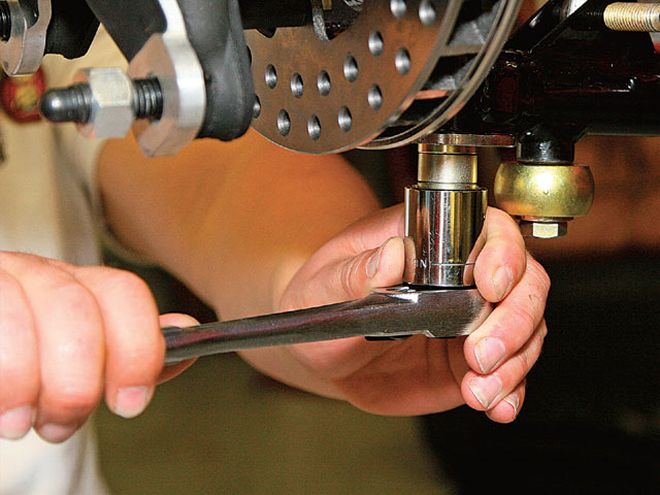 Along with changing the upper control arm angles, we also installed Mono-Ball ball joints in the lower control arms and spaced them to reduce the angle of the lower arms.
Pinion angle to the ground plane is useless if we don't also measure its relationship to the other driveline components. We started at the transmission and recorded a 1-degree angle with the tail down. The driveshaft measured 2.50 degrees (rear down) and the pinion was at 4.50 degrees down angle. So, our difference at the front of the driveshaft was 1.50 degrees to the transmission tail shaft and 2 degrees at the back of the driveshaft to the pinion shaft.
Our pull bar will be extending approximately 0.50 to 0.75 inches. We did some measuring and calculations and found that the rearend would be rotating to a maximum of 3.5 to 5 degrees. With this amount of rotation and pinion angle change, when the car is accelerating, the pinion, driveshaft, and transmission will be almost inline. Our experts tell us that this is the ideal situation for minimal power loss and therefore maximum rear wheel power.
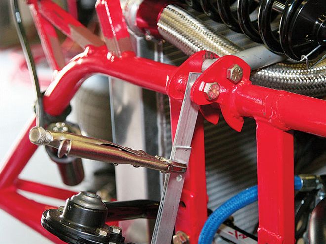
We set our panhard bar, which is mounted to the right side of the chassis as it is in all Rayburn cars, at 10 1/2 on the left and 13 1/2 on the right. The mounting of the bar on the right side chassis provides a more consistent feel to the driver and a more stable dynamic condition to the car.
This was first tried by Billy Moyer at my urging on a Rayburn car in 1997 at the Hav-A-Tampa Dixie Shootout, the final race of the top Dirt Late Model touring series held at Dixie Speedway in Woodstock, Georgia. I was just plain dumb about dirt cars back then, but I knew that moving the bar to the right side chassis would be more consistent. My buddy Dewayne Ragland insisted that I talk to Billy and he decided to try it on his Rayburn car. It worked quite well. He set fast time, won his heat and the Dash for Cash, as well as the feature race, which clinched his H-A-T championship for the year.
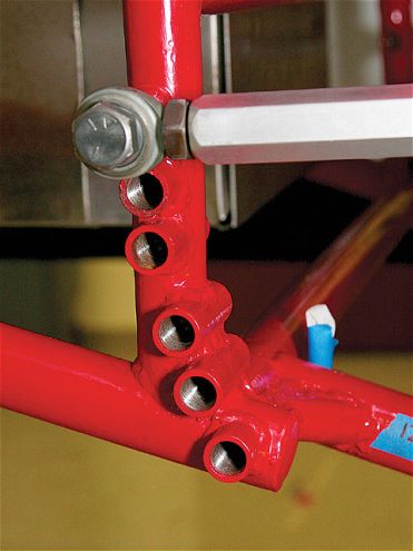 In keeping with our desire for less rear steer, we moved the rear links to holes that would make them more parallel to the ground.
Spring Setup
For springs, we needed to spring the car for North Florida Speedway, which would be our first race in the car. This speedway is a medium-banked track that I would estimate to be around 12 to 14 degrees. For this kind of banking, we would use a stiffer RF spring and a stiffer LR spring. Our layout (in pounds per inch) is: LF = 450, RF = 500, LR = 550 (220 equivalent), and RR = 650 (234 and 325 equivalent). The rates in parenthesis are the rate equivalent if the springs were mounted to a clamp on the rearend.
A note about the swing arm cars: A swing arm is one where the spring/shock is mounted on the control arm. This creates a motion ratio and a dynamic reduction in the rate the car "feels" equal to the spring rate multiplied by the square of the motion ratio. Our swing arms came with two holes and different lengths on each side. This created an opportunity for us to make changes to the spring rate the car feels just by moving the coilover to a different hole.
So, in the RR corner, we can start out the night with the coilover in the rear hole, which is the higher rate of the two, for an equivalent rate of 325 and then when the track goes slick move the coilover to the front hole for a 234 rate which provides more bite off the corners.
 All of the other holes would promote rear steer to move the right rear back and the left rear forward.
Weight Distribution
The final settings involve the weight distribution in the car. Our total target weight with the driver is 2,425 pounds with a 52.5 percent rear, 54 percent left side and 56 percent cross weight, or about 240 pounds of left rear distribution. Bobby won a heat race with that amount of LR weight and felt like this track could use a lot of LR load to help with bite off the corners. The option for a low range of cross is to go with 49 percent cross, or about 70 pounds of LR. We may well try that for tight conditions.
The rear percent is lower than a lot of the recommendations out there, but again, for this track we felt we needed to bring this car closer to a fifty-fifty distribution. The 54 percent left side is going to be good for tight conditions, but might be too much for a slick track. We might move more weight to the right side if the track conditions turn more towards being overly slick.
We had already moved all of the lead ballast to the middle of the car and some of it up higher to promote roll over and side bite. This might hurt us when the track is wet and heavy, but come feature time, it will be very helpful. Moving lead around is not so easy at the track and we will be developing ways to move weight up and down on a sliding tube to make changes to the center of gravity for changing track conditions.
Conclusion
At this point we are all set up to go racing. All we need now is to complete the installation of the body, fuel her up, and throw on some new tires. We want to thank all of our partners who have provided support for this project. We will be reporting on the results of our first race in the next issue, whatever the outcome.