
When choosing an engine to upgrade the performance of your classic truck there are a staggering number of options available from both major manufacturers as well as aftermarket engine rebuilders. Your choice depends on what you are trying to accomplish, be it a fire-breathing, blown big-block or a streetable, fuel-injected small-block.
Dressing up a late-model V-8 to emulate a design from decades past sometimes leaves you wanting more if you really want your engine to have that vintage vibe. On a recent visit to the Hot Rod Garage in Denton, Maryland, we came across an upgrade that shop owner Ray Bartlett designed to bring a bit of classic style to late-model Ford V-8s.
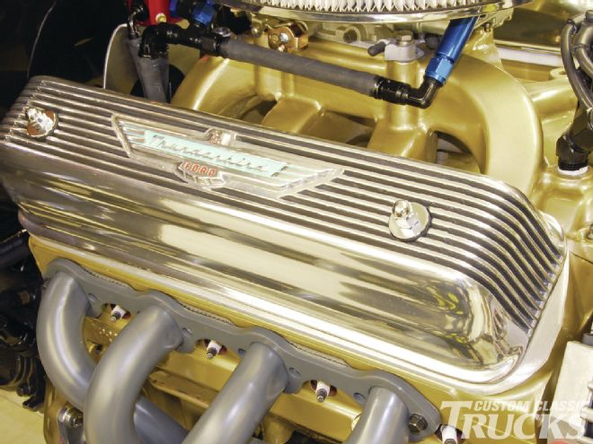
There’s nothing like opening the hood of your F-100 and seeing a set of early T-bird finned aluminum valve covers in place accented by other period-perfect elements. Problem is that the Y-block V-8 valve covers will not bolt to a late-model Ford V-8 as they both have different mounting systems. Leave it to the Hot Rod Garage to come up with a fix for that dilemma by designing a set of custom cylinder head adapter plates to make mounting them in place a snap.
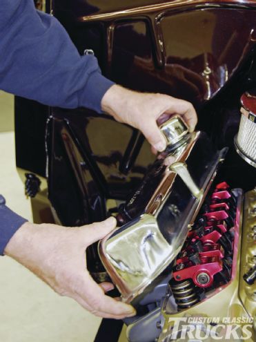
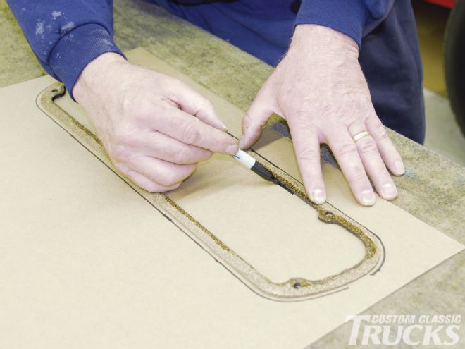
We followed team member Henry Steward as he got started by removing the stock-style valve cover, plug loom, and wires from the Proformance Unlimited-built 351ci Ford V-8. To create a simple template, a sheet of thin cardboard was used. The outside diameter of the valve cover and boltholes were traced first onto the cardboard stock using a black marker. The valve cover gasket was then carefully removed and used to trace the inside diameter of the cover. By doing this he was able to establish the inner seat of the valve cover where it mates to the cylinder head. Be sure to mark the template to illustrate the top of the valve cover to avoid any confusion.
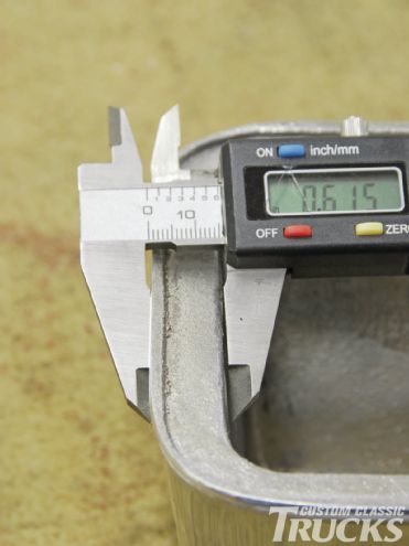
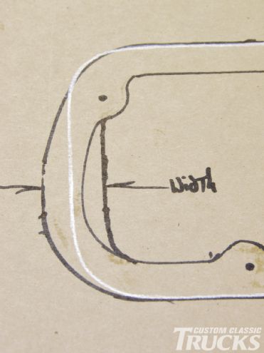
For the next step, a vintage Thunderbird Y-block valve cover was then placed onto the template to establish the difference in the outer diameter between it and the stock cover. To illustrate the difference, a white marker was used to trace its dimensions onto the template. It was easy to see from the first marking that while its horizontal planes were exact, its vertical planes were significantly inboard from the stock cover. A digital caliper was then used to establish the vertical width of the cover so as to complete the width of that plane at 0.615 inches. This completed the measurements needed for the template.
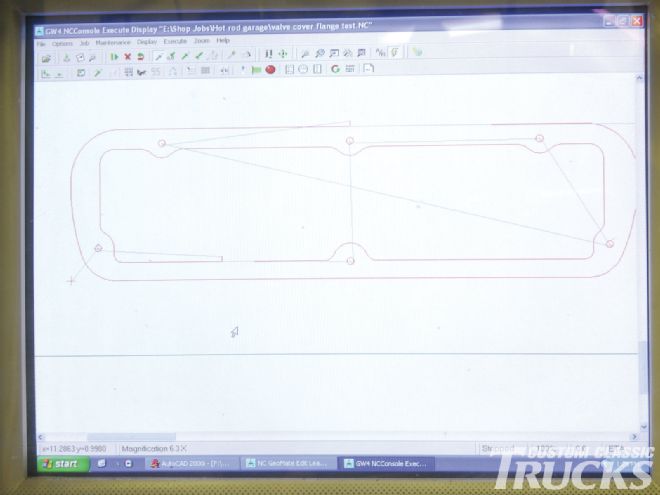
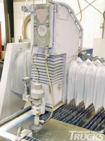
Lee Nash of Shore Fabrication, Inc. in Denton, Maryland, was then contacted to transfer all of the dimensions to an AutoCAD program and create a blueprint of the template. It was determined that the design should be transferred to a 3⁄8-inch 6061 strength aluminum sheet for strength and durability when mounting to the base of the cylinder head. To create the adapter plate, the program was transferred to a Calypso water jet with 60,000 psi cutting strength. Once Nash ran the program it was only a matter of minutes till the adapter plate was completed.
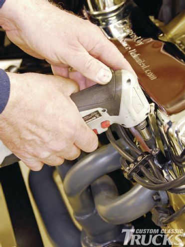
Once back at the Hot Rod Garage, the adapter plate was cleaned up and checked for fit atop the cylinder head. Since the plate needs to bolt flush to the head, it was determined that the six mounting holes would have to be countersunk. Steward addressed this using a Wilton drill press with a countersunk bit to allow the ¼x¾-inch-long stainless Allen bolts to be flush to the adapter surface. Once completed the plate was blown clean of any debris and test fitted to the head.
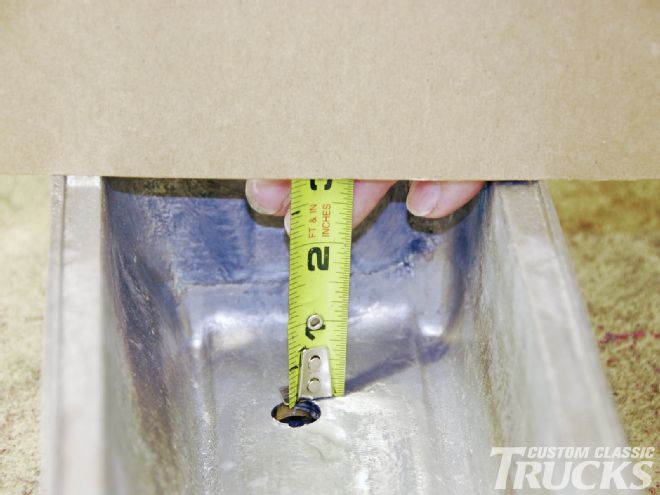
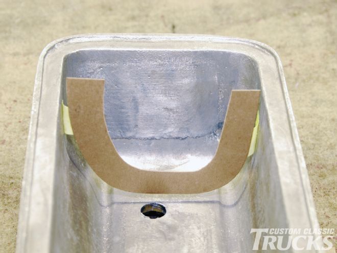
The final fabrication for the upright supports required fashioning a thin cardboard template from the interior area of the Y-block valve cover. It was important to first measure the interior depth of the cover. This was accomplished by laying a straight edge over the opening of the bottom of the valve cover and measuring the interior depth with a tape measure which equaled 27⁄8 inches. From there a U-shaped cardboard template was made which would work on either side of the valve cover.
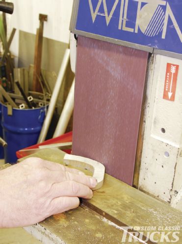
The section was then deburred using a Wilton belt sander and then blown clean of any remaining debris. It was then test fitted in place between the rocker assembly where the final trimming was noted for proper area clearance on the side plane as well as notches for the mounting base of the adapter plate. A graduated bevel cut of ¼-inch using a bandsaw was made to the left side plane for a perfect fit between the rocker assemblies.
The upright supports and valve cover were then mocked in place so that the mounting holes could be marked on the supports. These holes were drilled on a drill press using a 9⁄32-inch drill bit, then blown clean, and followed by a 5⁄16x24 thread tap used to complete the job to install 23⁄8-inch mounting studs. To complete the job, a custom stud spacer was bolted in place to retain the perfect alignment of the uprights to the adapter plate. The uprights were then TIG welded to the adapter plate.
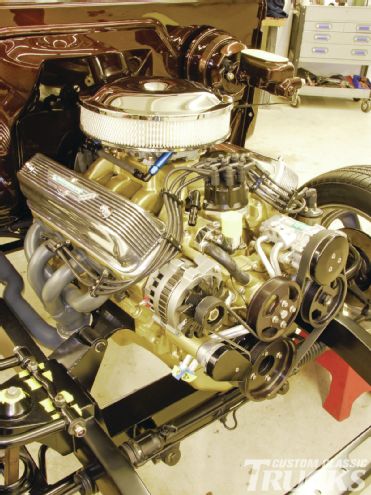
Once completed the adapter was bolted to the cylinder head and fitted with the Y-block valve cover gasket and cover. The final outcome was a perfect melding of the vintage good looks of the finned aluminum T-bird valve cover to the late-model Ford V-8. For further information on the availability of this conversion contact the Hot Rod Garage and tell ’em we sent you!
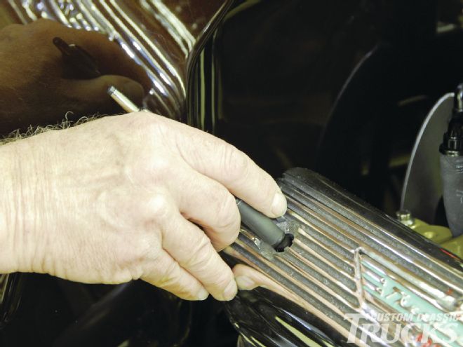
1-2. The first step was to remove the ¼-inch Allen bolts, chrome valve covers, and spark plug wire looms from the Proformance Unlimited 351ci Ford V-8.
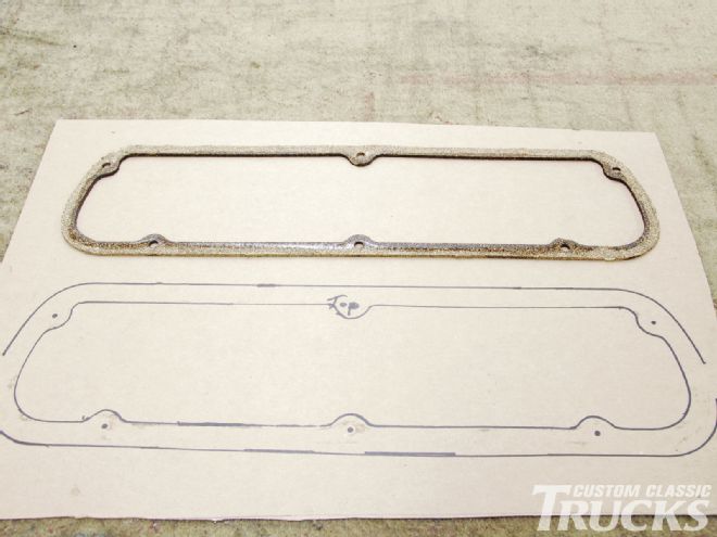
3. The outside diameter of the factory-style valve cover was then traced onto a section of thin cardboard stock.
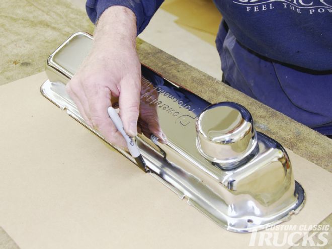
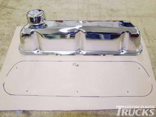
4. Here you can see the initial outline of the valve cover along with the boltholes highlighted.
5-6. With the valve cover gasket removed, its inside diameter was then traced to establish the interior seat of the valve cover on the cylinder head.
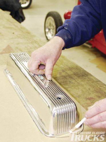
7. Using a vintage Thunderbird Y-block valve cover, a white marker was used to trace its outer diameter onto the template.
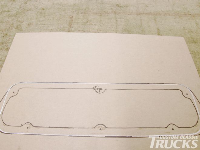
8. It’s easy to see the difference in the exterior diameter of the Y-block versus the late-model Ford V-8 valve covers. While the horizontal planes are exact, the vertical planes differ.
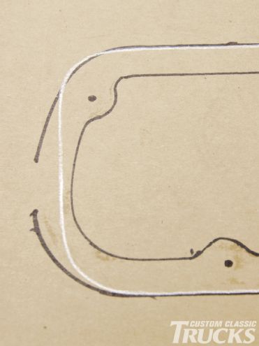
9. This shot lets you see a close-up of the exact dimensional difference between the two valve covers for mating the Y-block cover to the cylinder head.
10. The width of the Y-block valve cover-mounting surface was measured using a caliper with a digital readout confirming 0.615 inches.
11. With the mounting surface width confirmed, it was transferred to the template completing all of our needed measurements.
12. The completed template was then converted to an AutoCAD program by Shore Fabrication Inc., for use with its water jet cutting system.
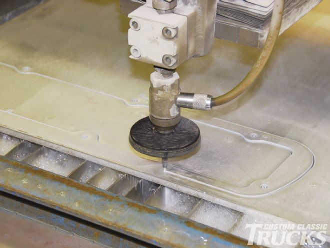
13. The Calypso water jet system is fully automated and uses 60,000 psi to cut through 3⁄8-inch 6061 strength aluminum making the job look effortless.
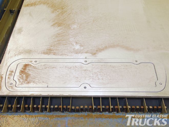
14-15. From start to finish took it only a few minutes till the adapter plate was completed.
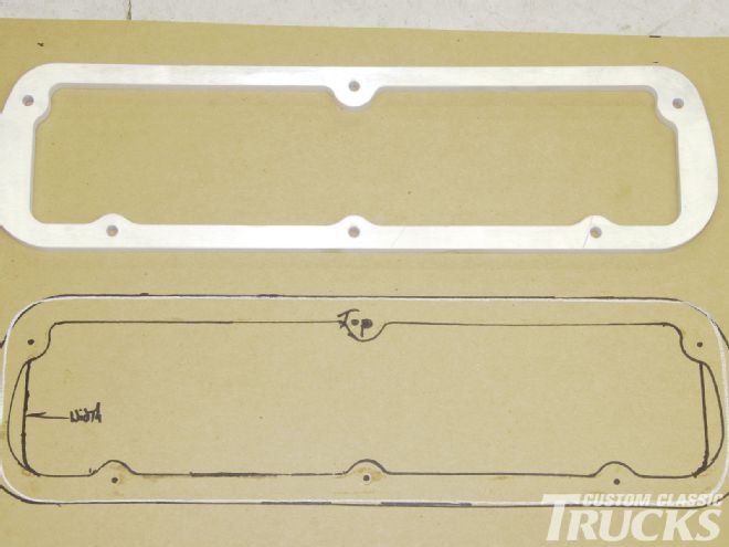
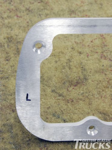
16. Once the new adapter plate was cleaned off you can see just how exact it was to the original template.
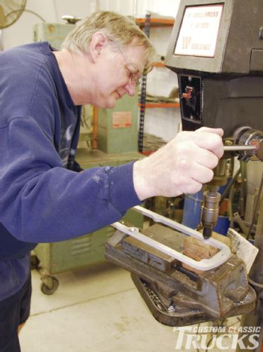
17-18. Since the adapter plate needs to mount flush to the cylinder head, Hot Rod Garage team member Henry Steward used a drill press with the appropriate countersink bit to prepare the mounting holes. The close-up image lets you see the mounting depth upon completion.
19. The adapter plate was then blown clean of any debris and then test fitted to the cylinder head using ¼x¾-inch-long stainless Allen head bolts.
20. With the adapter plate mounted you can now see how nice the overall fit to the cylinder head is. This lets you check for any additional adjustments to the adapter plate. None were needed here.
21. Next, it was necessary to take initial measurements to create a pattern for the upright supports of the valve cover mounting. Here the inside valve cover total depth is 27⁄8 inches.
22. A simple pattern was fashioned from thin cardboard stock illustrating the upright support dimensions. Note that Steward allowed for exactly ¼ inch from the inner cover surface to the top of the upright support stanchion.
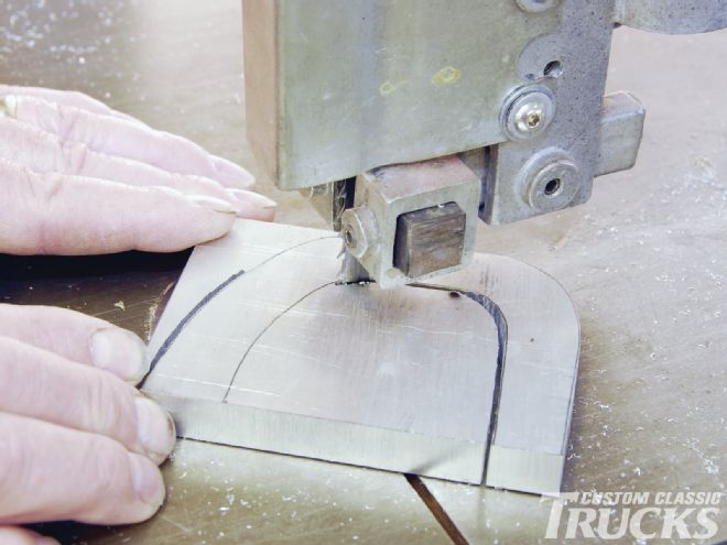
23. The pattern was then traced onto a piece of ½-inch aluminum plate and cut out on a bandsaw.
24. To deburr the stanchion, it was run across the base of a belt sander.
25. Steward returned to the bandsaw to cut a graduated bevel into the side of the stanchion as well as mounting base notches where it will meet the mounting plate.
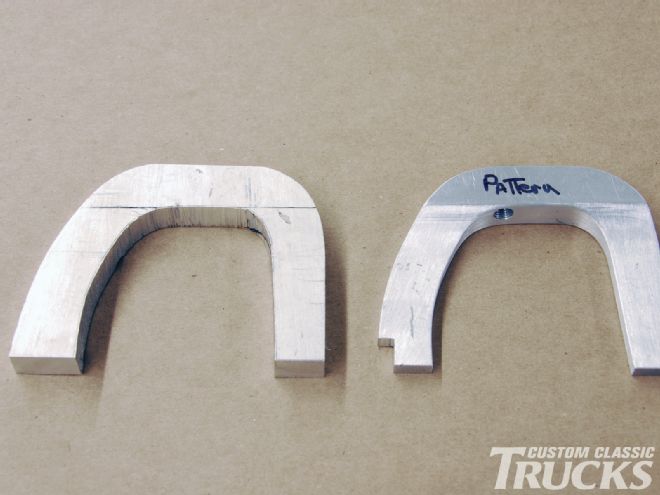
26. Note the difference between the initial stanchion (left) and the completed one (right). The ¼-inch offset bevel to the side of the stanchion allows the unit to carefully fit between the rocker assemblies to the adapter plate base.
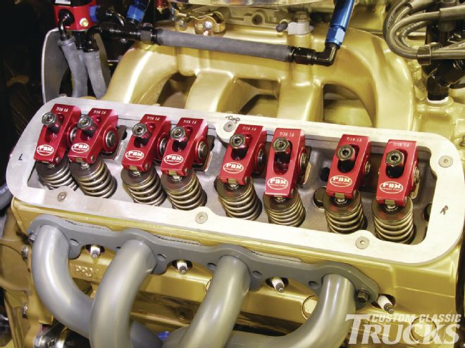
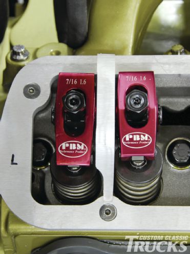
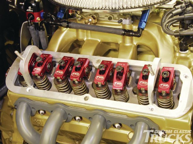
27. Here you can see the upright support mocked in place perfectly fitting into its close confines with ample rocker clearance.
28. The Y-block valve cover was then carefully set in place and a black marker was used to secure the left and right mounting holes.
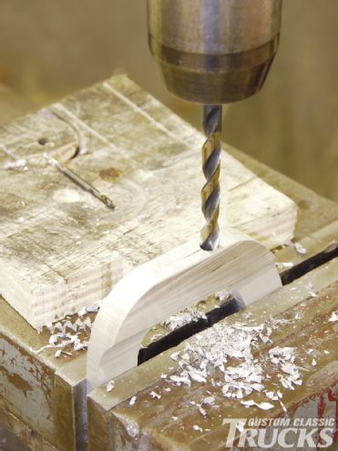
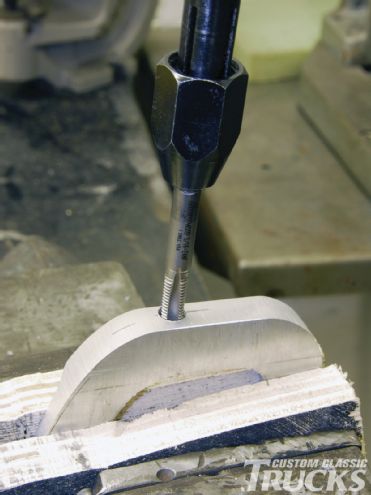
29. While secured in a vise, a 9⁄32-inch drill bit was used to drill the stanchion top mounting hole.
30. The hole was blown clean and a 5⁄16-24 thread tap was used to complete the job to install 23⁄8-inch mounting studs.
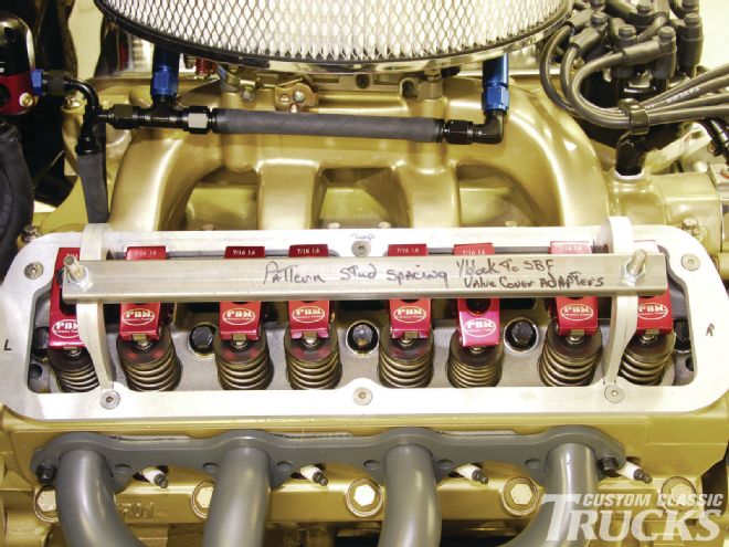
31. To prepare the adapter base and upright stanchions for welding, a stud spacer was bolted on to keep everything exactly in place.
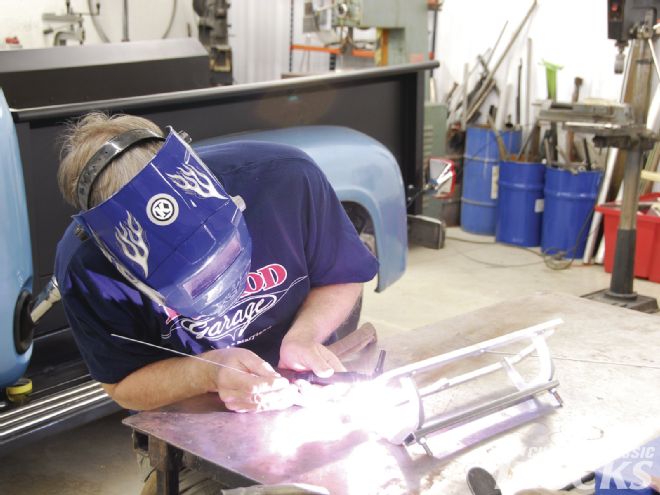
32. Steward then TIG welded the upright stanchions to the adapter base.
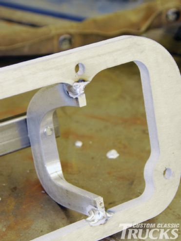
33. Here you can see the completed welding prior to the stud spacer being removed.
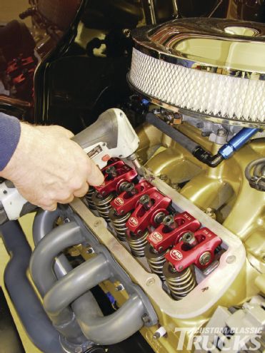
34. With the adapter plate mounted to the cylinder head, all that’s left is to complete the installation of the remaining Allen mounting bolts and valve cover.
35. The outer edge of the mounting plate will later have its edge feathered down to give the transition a nice sleek look. Once color matched to the cylinder head it will practically disappear.
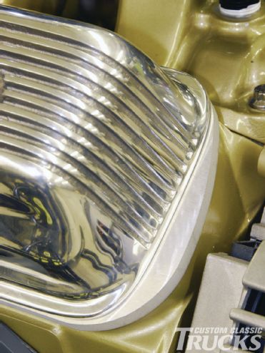
36-37. Presto-chango, with the classic Y-block finned aluminum valve covers in place the late-model Ford V-8 takes on a vintage look and feel that will keep plenty of car owners guessing. That’s the grand illusion!