 The valvetrain of a cam-in-block, overhead-valve engine is a complicated assembly of many parts. All components must work together effectively in order for your engine to make maximum power.
There's no doubt that the valvetrain is the most complex part of any racing engine. It's also pushed the hardest against some incredible stresses. Nextel Cup teams and some manufacturers are putting tremendous amounts of resources and some pretty innovative research systems into place to advance the science of the racing valvetrain, and the things they are learning are quite interesting.
One of the companies leading the development front is Comp Cams, which not only works with many Nextel Cup teams on their engine programs but also has its own R&D program that it uses to advance its products used by the Saturday night racer. Comp's engineers have pushed the use of the Spintron machine and complex mathematical models to better understand what's going on with all the various parts of the valvetrain when the rpm starts creeping into the upper limits. This story isn't a rehash of all the stuff you slept through in physics class in high school. Instead, there's a lot of practical knowledge that can be learned-and used right away-by the computer modeling and Spintron testing done behind the scenes at Comp's R&D lab.
Thomas Griffin, who is one of Comp's lead design engineers, says that one of the keys to finding ways to improve the valvetrain is to be able to look at it as an entire system. He points out that an engine is comprised of many interrelated systems. For example, the ignition system is made up of the distributor drive gear, the distributor shaft, rotor, cap, wires, plugs, and coil. Each piece is required to ignite and burn the air/fuel charge in the combustion chamber. If one piece is missing, the entire system fails to work. Likewise, if one piece of the system is functioning poorly, the performance of the entire system will suffer.
The same holds true for the valvetrain, which is made up of more components than any other system. In a pushrod-style engine (typical for oval track racing), this system is comprised of the drivebelt or chain, camshaft, cam lobe profile, lifters, pushrods, rocker arms, valvesprings, valves, retainers, and locks. Just like with the ignition system, all the parts of the valvetrain must work individually and together as a complete system. This duality of roles can cause problems that are often missed. Griffin says that it isn't uncommon to make a change to a component-say a valvespring retainer-that is an improvement (maybe a reduction in weight, or an increase in strength). But when that "improved" component is added to the system, overall performance suffers.
This is because our new "improved" piece doesn't play well with others. This doesn't mean that the new part is a poor choice for every valvetrain system, just this specific one it was tested with. Because there are so many variables involved (everything from lash to the stiffness of the pushrods to the weight of the valves), you can never assume that identical changes to similar valvetrains will produce identical outcomes.
As an example, Griffin points to a test in which lighter valves were used in a Spintron test to try to achieve better valve control at high rpm levels. This is proof that sometimes when an individual component is changed, the system result is something other than what is desired. This is because it can often be hard to predict how the new combination of components will react with one another.
Individual Components versus the System
Reducing component weight is one of the Holy Grails of most engine builders because it often allows increased engine speed. Unfortunately, one of the side effects that often comes from reducing the weight of a component is decreased rigidity. This means it is more easily bent or twisted, and it also changes that object's natural frequency. The natural frequency of an object is the rate at which it vibrates. We'll delve deeper into the importance of natural frequency a little later.
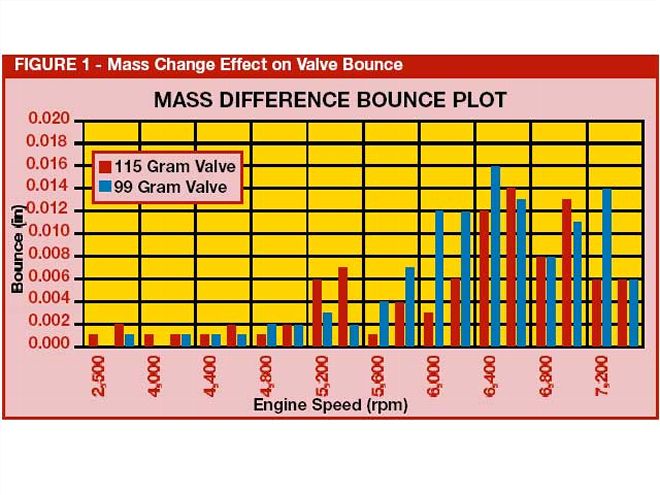 FIGURE 1 - Mass Change Effect on Valve Bounce
In the following two illustrations (Figures 1 and 2), Griffin tracked and compared the amount of valve bounce of two different valves at different engine speeds. In the first figure Griffin compareid two steel valves, one weighing 115 grams and the other weighing just 99 grams. At first, you would think that the 99-gram valve would behave better because its lighter weight should mean that it would be more easily controlled by the spring. This, however, isn't the case. The lighter valve exhibited significantly more bounce between 5,600 and 7,200 rpm. There can be many reasons for this, but the most probable is that the thinner head of the lighter valve provided a "springing" action when it was pulled against the seat, creating a bouncing effect.
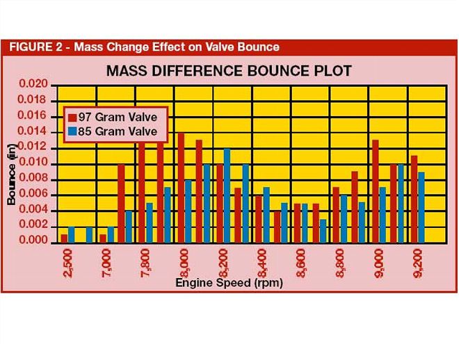 FIGURE 2 - Mass Change Effect on Valve Bounce
In Figure 2, the same test has been performed with two titanium valves, in this case weighing 97 and 85 grams. Here, Griffin explains that the amount of bounce changes with engine speed in two ways. First, the bounce is reduced almost everywhere. Second, the speeds where the bounce is greatest is different. In this case, the lighter valve seems to help where, in Figure 1, this isn't the case across the entire rpm range.
The same type of surprises can also be found with valvesprings. Comp Cams has tested an untold number of different valvespring combinations, and the results show that a group of springs that measure the same on the seat and over the nose don't produce the same results.
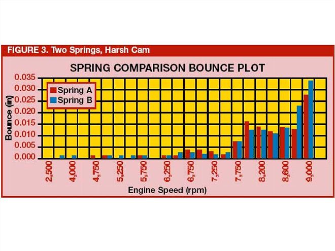 FIGURE 3 - Two Springs, Harsh Cam
In racing, the double spring is most commonly used because it allows for greater combined spring pressures. What many people don't realize, however, is that different springs can use different combinations of inner and outer springs to achieve the same total pressures. In other words, two sets of springs may measure the same when checked as assemblies, but when you break them down into individual components and compare the two inner springs or the two outer springs, they may be completely different. The weights, stiffness, and natural frequencies may all be different. Griffin provided this graph (Figure 3) plotting bounce with two different springs that check out the same as complete assemblies but are quite different as individual components. This is why a spring set from one manufacturer may have all the same specs as one from another manufacturer but behaves completely different than the other set once it is installed in an engine that's in a race car or put on a dyno. It's not until you break everything down to the individual component level that the real reason for the performance difference becomes visible.
Finally, Griffin says the same thing holds true for camshafts. A cam profile that produces horsepower or rpm gains in one engine may reduce power in another with a different valvetrain setup.
"For instance, a little more peak positive acceleration on the profile in one engine might pick up the power over the entire operating speed range. Applying the same philosophy to a cam profile in another engine might hurt the power all over the board and make the engine lose a few hundred rpm," says Griffin.
Understanding Vibrations
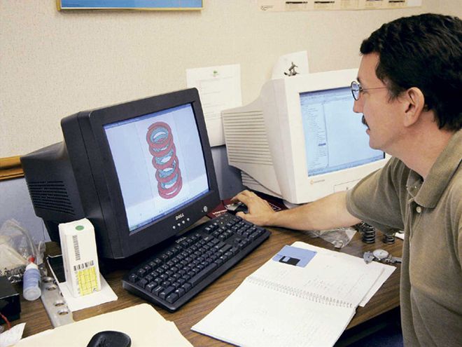 Engineer Thomas Griffin studies a mathematical model of one of Comp's valvesprings.
Understanding how a valvetrain will react at very low rpm levels is relatively easy. At low rpm levels, the inertia in all of the various components does not come into play as they move. Predicting how a valvetrain will behave at 1 rpm-or even 1,000 rpm-is relative child's play compared to predicting what will happen to that very same valvetrain at 7,000 rpm.
At higher rpm levels, the speed at which the valvetrain moves is much greater. The inertial forces acting on every component comes into play in a big way. "At slow speeds when the valve is opening and closing, compressing the valvespring is the main activity that creates a force in the valvetrain," Griffin explains. "As the engine speed increases, the pushrod and rocker arm are required to move the valve and compress the valvespring at a faster rate. When this happens, the magnitude of the forces seen in the valvetrain increases. The additional inertia force causes more deflection in the components than the force of the valvespring alone. To aggravate the situation even more, because these forces are cyclical, vibrations can occur in the components." In other words, at high rpm you have to consider the valvetrain a system of vibrating components.
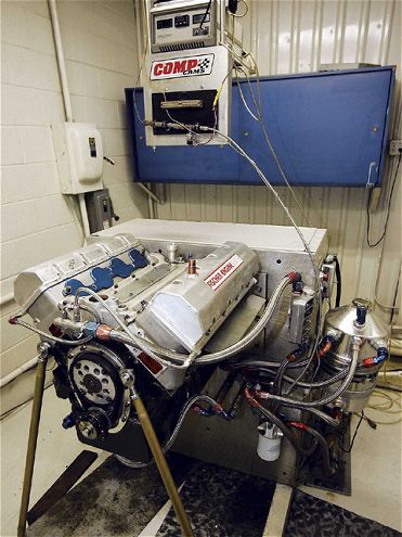 Comp's Spintron cell is a vital part of the company's R&D program and is one of the only ways to analyze specific components of a valvetrain while it is working at speed.
By definition, a vibration is a motion that happens repeatedly within an object. It is measured by how frequently this repeated motion occurs within a period of time (hertz). Every object has its own natural frequency, or the speed at which a vibration will travel through it. When the speed of the input causing the vibration (engine rpm) matches the natural frequency, the vibrations build upon one another, gathering strength each time. This can be very damaging to the component and even the components attached to it. Likewise, it is also possible that the cause of the vibration can be timed to conflict with the component's natural frequency so that the two cancel each other out. By working with a general understanding that the valvetrain is a system of vibrating components, we can work to mix and match the components (and their natural frequencies) to minimize the effect of vibrations on the system. The result is more dependable performance, better valve control in the upper rpm ranges, and increased component life.
A good example of how vibrations can alter the intended performance of a component is the change in loading on a pushrod as the rpm changes. As the cam begins raising the lifter and pushrod, the pushrod sees a spike in load as it tries to overcome the inertia stored in the mass of the rocker arm, spring, valve, retainer, and locks. The loading drops once those components begin to move, and there is a vibration that travels up and down the length of the pushrod. At the 7,000- and 8,000-rpm levels, you can see how radically the loading changes on the pushrod versus the lower rpm levels. Griffin says the vibratory waves also grow and contract with respect to crankshaft rotation as an effect of the pushrod interacting with other components. This is one reason many engine builders are going with larger pushrods in high-rpm applications. Even though you might think the lighter weight in a smaller pushrod would be more beneficial at high rpm, it is often actually better to go with a stronger (and thus, heavier) pushrod that exhibits less deflection as a result of these loading forces.
 You might think a rocker arm is a solid body, but it actually becomes flexible at high rpm levels, as Comp's technicians have found from SpinTron testing.
When you consider the effect of vibrations on the valvesprings, it gets even more interesting. Valvesprings have flexibility, so they suffer from the largest deflections because of vibrations. Not only that, but the frequency of the vibrations (and the loading on individual coils) changes because the coils actually collide and create a force spike that changes the shape of the vibration wave as the valve is opening. This can cause a phenomenon called "spring surge," which is a major culprit behind the loss of valve control in many racing engines. When allowed, progressive rate springs are very effective at controlling this. They actually utilize the closing up of the active coils in the spring to damp out vibrations due to spring surge.
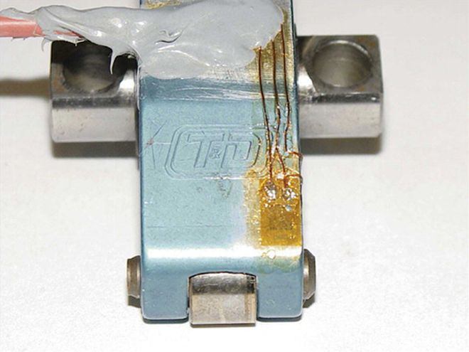
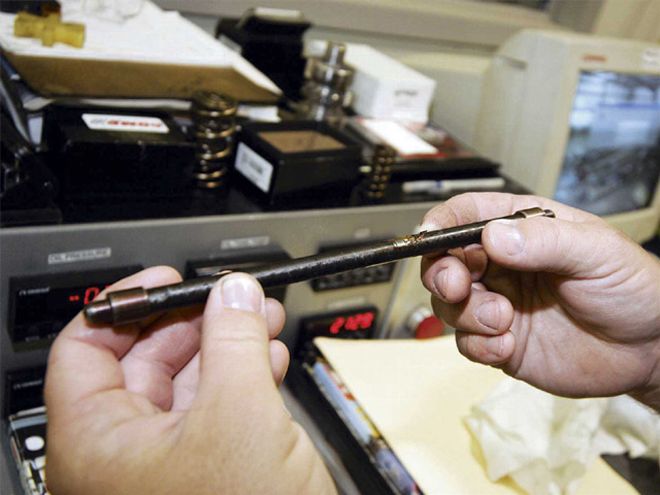 This pushrod has been prepped with a strain gauge before being used in a Spintron test. By detecting changes in the conductivity of the metal forming the pushrod, technicians can tell if the pushrod is flexing and by how much.
Of course, we don't want to go too much deeper into this or we will quickly reach the point where racers will become frustrated physics students. We'll leave the actual mathematical models to the engineers who drool over that kind of stuff. The point here, whether you are an engine builder or a racer who simply wants more power ( who doesn't?) is that many problems caused by poorly matched valvetrain components are mistakenly blamed on other parts of the engine. If the engine is lying down at half-track, don't automatically assume that the heads are too small or the ports need more work. It could be that poor valve control caused by vibrations is keeping the engine from working as efficiently as it can.
Always Test, Never Assume
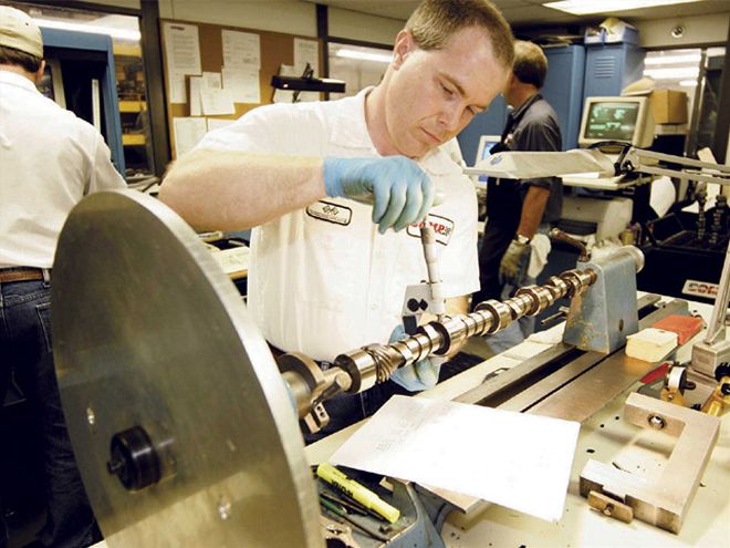 Although two camshafts may have identical lobe profiles, they aren't necessarily interchangeable. Such "minor" things as the cam's barrel diameter (shown being measured here) can play a major role in how the valvetrain behaves at speed.
While helping Circle Track with this article, Griffin also gave us the following example of how assuming anything when it comes to the valvetrain can lead to trouble. Sometimes, it just makes you feel better to know that even the Cup guys make mistakes.
"The pressure to reach higher engine speeds and more valve lift is always present. In a particular case several years ago in the Nextel Cup world, the approach for some engine builders was to take some existing cam profiles and throw more and more rocker ratio to them to achieve this goal. The word got around through the garage that the Chevy guys were able to do this, so quite obviously, the Ford guys tried it.
"But the same combination of parts that were running in the Chevy engines didn't work out quite the same in the Ford engines. The cam profile, the pushrod, rocker arm ratio, and valvespring were all the same, and the weight of the valve, retainer, and locks were all the same. The assumption that everything here is the same was proven incorrect, though.
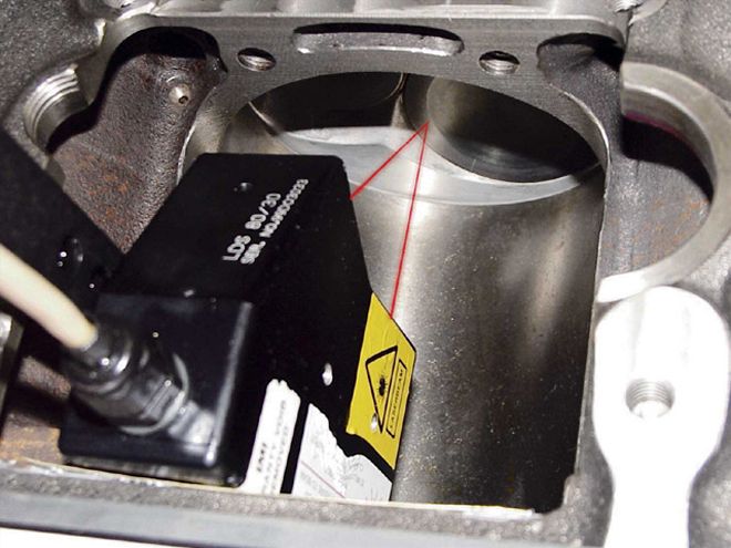 Because there are no pistons moving up and down inside the block setup on the SpinTron, a laser can be used to track valve bounce as an electric motor spins the camshaft and the rest of the valvetrain through the rpm range to be tested.
"The barrel size of the two camshafts were different, and the geometry of the valvetrain components were different. The valvetrain is a system of components that must be properly selected to operate in a violent environment, and a poor-but common-assumption is that the valvetrain is insensitive to subtle changes. The Ford engine pushed the limits of valve bounce farther than the components allowed. What's bad is that the Ford valvetrain customer failed a few valvesprings in a couple of races before getting around to testing the setup on a SpinTron."