The Advance CurveAll engines require an ignition curve based both on the requirements of engine rpm and cylinder filling (volumetric efficiency). This means that at 3,000 rpm with the throttle open only 10 percent, the engine's timing requirements will be different than at that same rpm at wide open throttle (WOT). This is because cylinder pressure is much higher at WOT than it is at part-throttle with a lower cylinder pressure requiring more time to complete the combustion process compared to a more highly pressurized cylinder.
Based on this variable timing requirement, all engines use a three-tiered formula for creating an optimized ignition curve. Combining initial timing with mechanical and vacuum advance creates a curve that will satisfy all of the engine's various operating requirements. Initial timing sets the base timing that is present as the engine cranks and at idle. Mechanical advance adds more timing as engine rpm increases. Vacuum advance is added to the combination of initial and mechanical at light engine loads when vacuum is highest to ensure optimal fuel mileage and efficiency.
Initial TimingAll engines start off with a base timing figure called initial timing. This is established with the physical position of the distributor in relationship to the engine. Ignition-timing figures are always delivered in crankshaft degrees and in relationship to the No. 1 piston at top dead center (TDC). This means that any ignition advance will be expressed in terms of degrees before TDC (BTDC). This is important because some enthusiasts get confused when viewing timing markers on engines where the timing tab may be embossed with ATDC and BTDC. The confusion here is that some people mistakenly think that the "A" in ATDC means "advanced" when it really means "after," as in "after top dead center."
Now that we have that straight, initial timing is the setting for the number of crankshaft degrees BTDC that the spark plug fires. For most performance street engines, that figure will generally be between 10 and 18 degrees BTDC. This is set by loosening the distributor holddown bolt and twisting the distributor housing while watching the timing mark on the crankshaft using a timing light. The key here is to twist the distributor in the proper direction. For most GM engines, the distributor turns clockwise. So to advance the initial timing, you must move the distributor against rotation (counterclockwise). To retard the timing, you would twist the distributor with rotation (clockwise). If you're not sure which direction the distributor turns, you can remove the distributor cap and crank the starter and watch the rotor.
Initial timing is added directly to both vacuum advance and mechanical advance. So if you have an engine that prefers more initial timing, this may require some adjustments to the mechanical-advance mechanism to accommodate the additional timing. Engines with long-duration camshafts and low-idle manifold vacuum benefit the most from more initial timing, while near-stock valve timing responds poorly to excessive initial timing. So the rule of thumb is more initial timing for engines with big cams and less for stock-cammed engines.
Mechanical AdvanceHere's where most of the magic lies. As engine speed increases, there is less time for the combustion process to take place. In order to create maximum cylinder pressure at higher engine speeds, its necessary to start the combustion process sooner.
This is accomplished by creating a mechanical-advance system based on engine speed. As engine speed increases, the "lead time" increases up to a point. If you recall the timing graph from earlier in this story, you can see that mechanical advance starts from the initial timing point and adds more timing as engine speed increases up to just under 3,000 rpm where it should level out. This is a typical street engine ignition curve.
Most domestic distributors create this curve by employing a pair of weights and small springs that are placed on a pedestal attached to the distributor shaft. As engine speed increases off idle, centrifugal force swings the weights away from their pivot point. This twisting movement also moves the position of the spinning pole points that swing past the electronic pickup, which advances the timing. The distance the weights travel is determined by a pin that travels through a slot. The distance the pin travels determines the total mechanical advance. For aftermarket distributors like an MSD, the pin is fitted with an interchangeable bushing. A thicker bushing limits the total amount of mechanical advance while a thinner bushing allows more.
The rate at which the total advance is achieved is determined by the strength of the two small springs. Heavier springs create a very slow curve while light springs allow a very rapid rate of timing increase. So the engine tuner has the opportunity to vary not only the total amount of timing, but also the rate at which the timing is achieved. As the graph shows, a typical street mechanical-advance curve will all be in by roughly 2,800 rpm.
For a street engine, you might think that more is better and that a quicker curve with very light springs is a good thing. But very light springs can cause other problems, such as causing clutch chatter when leaving from a stoplight, because the advance begins too soon and comes in too quickly.
Conversely, an engine with high static compression on pump gas might want a slightly slower advance curve to keep the engine out of detonation. Each engine has its own timing requirements and the only way to know for sure is to experiment with different springs to find a curve that works. The good news about this is that this only requires time and no expensive tools or parts.
Vacuum AdvanceUnder light-load cruise conditions, the mostly closed throttle minimizes cylinder filling. This creates reduced cylinder pressure. Ideal timing for this situation requires advanced timing in order to complete combustion before the exhaust valve opens. Since a mostly closed throttle also builds high manifold vacuum levels, vacuum can be used to produce additional advance through a diaphragm device called a vacuum-advance canister.
Before we get into the actual components, it's important to make sure the vacuum signal from the engine is correct. Most carburetors offer two different vacuum sources. The simplest is straight manifold vacuum, while the one you want for vacuum advance is called ported manifold vacuum. This source is designed so that the vacuum signal only occurs after the throttle blades are slightly open, which means there is no vacuum signal at idle. This ensures the engine idles on only initial timing and not the combination of initial and vacuum advance.
Most vacuum-advance cans add between 10 and 20 degrees of advance with the highest vacuum producing the most advance. As the vacuum signal drops (as the throttle opens), this reduces advance until WOT is achieved at which time minimal manifold vacuum is present and vacuum advance is zero.
Vacuum advance merely improves the part-throttle experience and is especially important in street driving since 90 percent of it is at part-throttle. Of course, it's possible to add too much advance. Generally, excessive timing will create a light surge or even detonation. Too little vacuum advance is not as clearly defined and will require experimentation to determine the ideal amount of vacuum advance.
Timing LightsThe best way to measure total mechanical and vacuum advance is with a dial-back timing light. These more expensive lights use a dial on the back to place the TDC mark on the harmonic balancer at the zero timing mark on the engine. Then you merely read the total amount of timing on the dial. These lights are more expensive and can sometimes introduce a slight delay in timing accuracy.
For those on a budget with only a more generic light, the easiest way to read total timing is to attach a timing tape to the harmonic balancer. MSD makes a series of inexpensive timing tapes on a sheet with different tapes for specific balancer diameters. These tapes adhere to the balancer and produce easy-to-read figures. It doesn't really matter which timing light you choose to use, as long as you always use the same light to set the timing on your engine. Mistakes occur when you use a different light each time. We've seen lights vary by as much as three degrees on the exact same engine at the exact same rpm.
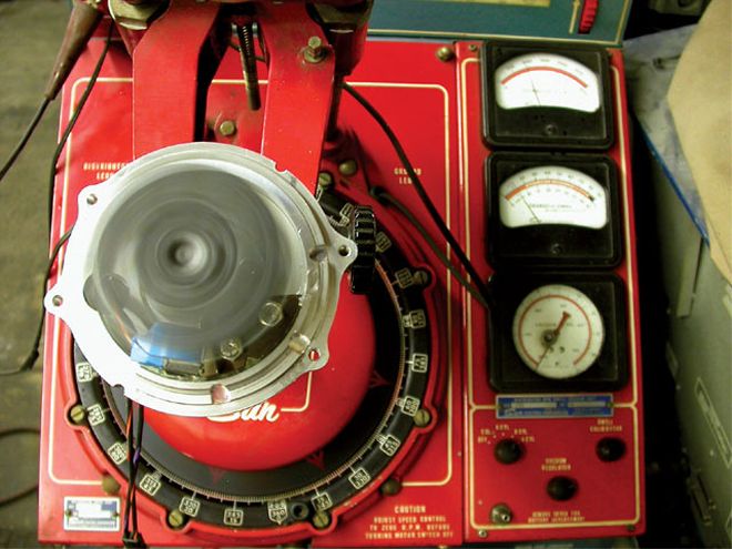
Checking The CurveMany car crafters think they have to put their distributor on a machine to determine the timing curve. While this does work, it's also possible to create a timing curve with the distributor still in the engine. To do this, you'll need a timing light, timing tape, a tachometer, a paper and pencil, and a buddy just to make things easier. Here's the drill.
First, unhook the vacuum advance and measure initial timing. Let's say it's 10 degrees at 900 rpm. Next, rev the engine to 1,500 rpm and measure the timing again. Now let's say it's 14 degrees. Record the timing in 500-rpm increments until the advance numbers no longer increase. Let's say the curve looks like this:
Initial 10 2,500 26 1,500 14 3,000 32 2,000 20 3,500 32Now let's reconnect the vacuum advance and redo our test and the results look like this:
Initial 10 2,500 38 1,500 20 3,000 44 2,000 32 3,500 44Now let's say you really want to have 36 degrees of total timing without the vacuum advance, so you add 4 degrees of initial timing. For fun, let's say that this makes your WOT timing curve perfect, but now the engine surges at part-throttle because you have 48 degrees of total timing with the vacuum advance. The best bet would be to braze or epoxy the slot closed slightly in the vacuum-advance canister (you should remove the canister from the distributor to do this).
By balancing initial, mechanical, and/or vacuum advance, you can create your own custom advance curve tailored specifically to your engine and drivetrain combination. The best part of all this is that you don't have to spend a bunch of money to do it. All it takes is a little time and effort.
Quick TechNeed to do a quick check on the ignition curve on a buddy's engine, but you don't have a timing tape or a dial-back timing light? We'll show you how to make a homemade timing tape, look like a tune-up pro, and amaze your friends all at the same time. All you need is to measure the harmonic balancer diameter, determine the circumference (3.1417 x diameter), and then divide that dimension by 180. This will give you the distance equal to 20 degrees. We've listed the dimensions for four popular balancer diameters so you don't have to do the math:
Balancer Distance/ Diameter Circumference 20 Degrees 8.00 25.1336 1.396 7.50 23.562 1.309 7.25 22.777 1.265 6.50 20.421 1.134The quickest way to make the tape is to establish the TDC or 0 line and use a dial caliper to establish 2-degree increment lines from 10 degrees to 40 degrees. Then stick the tape to the balancer so that the TDC lines overlap and you're ready to go. It's that simple.
PARTS GUIDE DESCRIPTION PN SOURCE PRICE Crane distributor, Chevy 1000-1501 {{{Summit}}} Racing $319.95 Crane distributor, {{{Ford}}} 1000-1601 Summit Racing 319.95 MSD Pro-Billet distributor 8361 Summit Racing 227.88 MSD programmable timing 8981 Summit Racing 211.88 MSD Digital 7-Plus 7520 Summit Racing 564.88 MSD advance kit 8464 Summit Racing 12.88 MSD timing tape 8985 Summit Racing 3.88 ACCEL adj. vacuum adv. 31034 Summit Racing 21.95 ACCEL advance curve kit 31042 Summit Racing 11.99 ACCEL advance kit, HEI 31041 Summit Racing 11.99Electronic OptionsThere are several more high-tech ways to establish a very accurate and infinitely adjustable ignition curve that, of course, involve digital technology and bigger budgets. Crane, for example, has a street-oriented distributor for both Ford and Chevy motors that employs a fully electronic ignition-timing control unit. You choose from nine different mechanical-advance and three different vacuum-advance curves, dial them in on the face of the distributor, set your initial timing, and you're done. You can change these curves at any time very quickly. It's slick.
MSD also offers several options that start with the expensive but powerful programmable ignition-curve boxes such as the Digital 7-Plus and then down to Multi-Function ignition controllers, Vari-Curve controllers, and even simple digital retards for boosted or nitrous systems.
Ignition timing is a powerful way to control any engine but also to prevent the engine from damage as with knock retards. Understanding how all these systems work is a great way to get a leg up on making more power while ensuring that you're not going to break the motor just because the timing curve wasn't perfect. It all comes down to how much effort you want to put into making power.