
Among the systems that get very little attention in any performance car is the electrical system. For the most part, electrical systems function fairly efficiently, but there have been many advances over the last 30 years, so there are several areas that could stand improvement. Let's go over some of these and what you can do to make the electrical and charging system perform up to the level of the rest of your performance ride.
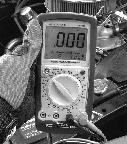 The most important tool in your electrical drawer should be some kind of digital multimeter. This is an Actron multimeter that can test for DC and AC volts, ohms, and continuity, as well as measure engine rpm and dwell. This is the Actron Auto Scanner model CP7677 available through Summit for $53. Actron also offers less expensive multimeters for the budget conscious.
Charge It
The basic automotive electrical system employs a battery, starter, and alternator. The alternator is the heart of the system, since without it, you won't get far. Early alternators were a vast improvement over their DC-generator forebears, with most alternators cranking out a maximum of 60 to 70 amps. This was because they were only asked to power the headlights, heater, and maybe an AM/FM radio, and none of these demanded high-amperage output at low speeds. But today's cars usually include air conditioning, high-output electric fuel pumps, and twin electric fans, not to mention a thumper stereo and other electrical accessories. So high-amperage output at low engine speeds is now in great demand.
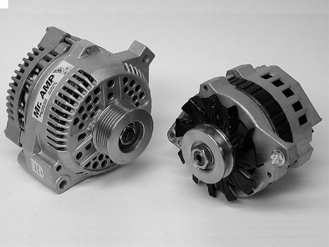 Late-model alternators like these smaller, more compact units are the hot ticket to creating sufficient amperage to run all those hungry electrical accessories. Late-model alternators are designed to create very close to maximum output at very low engine speeds.
Given this increased demand, late-model internal regulator alternators are now designed to pump near-maximum output at idle. This is a great reason to switch to a later-model-style alternator that can handle the load of a typical electronically enhanced street machine. Add up the load of a pair of 20-amp electric fans, a big electric fuel pump, headlights, heater or A/C fan, and a few amps for the stereo and you're looking at a load in excess of 60 amps. This is far greater than the max output of a '60s alternator. There are several companies now delivering high-output alternators, including Powermaster, Bosch and Performance Distributors, as well as the OEM's. Don't be fooled by the small diameters of these late-model alternators. These smaller units are capable of 100 amps or more output even at relatively low alternator speeds.
 Fusible links were used on '60s GM cars to protect the electrical system from a direct short or overload. The links are designed to melt if excessive amperage is pulled through the wire. These fusible links are often eliminated, which creates an opportunity for a wiring meltdown and perhaps a fire. The links are located between the positive battery terminal and the main feed-terminal junction.
Some confusion exists in the area of one-wire alternators. These are self-energizing alternators that do not require a separate feed-wire connection to energize the alternator. The term "one-wire" comes from the fact that the heavy alternator charge wire is the only wire connection required to the alternator. Most factory alternators are generally three-wire connections with a pair of small wires that complete the control circuit.
OEM style internal regulator alternators use an external 12-volt connection to signal the alternator to begin charging the moment it begins to spin. One-wire alternators instead rely on attaining a given internal speed to create a sufficient internal voltage to begin the charging process. One-wire alternators need to achieve a sufficient rpm to begin charging, usually around 1,500 to 1,800 engine rpm. So the only thing you have to remember when using a one-wire alternator is to lightly rev the engine once after starting in order to trigger the charging circuit. Some companies like MAD Enterprises suggest that the one-wire alternators do not do as good a job of maintaining system voltage and can be difficult to replace in the field, which is why MAD suggests using a three-wire alternator instead.
Grounded for Life
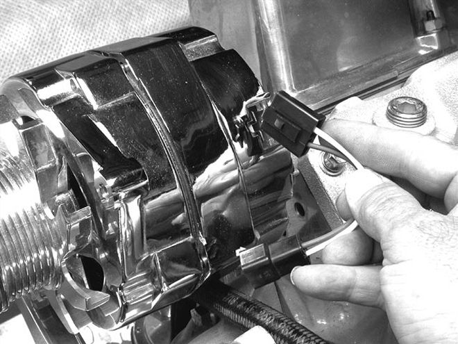 M&H Wiring Fabricators makes a slick late-model conversion kit that converts '63-'72 GM external-regulator alternators to an internal-regulator alternator. This slick conversion does not require cutting or splicing any wires and uses adapter plugs to do the job. The biggest task is mounting the alternator.
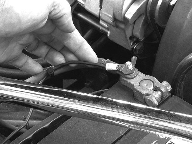
Another important area within the electrical system that rarely gets attention is the ground circuit. Even the simplest electrical circuit requires a power source, wiring that connects to a load (like a lightbulb), and wiring to complete the ground circuit back to the battery. But when performing electrical-system repairs, it's the ground circuit that is often ignored. The classic example of this is a dragging starter that begins after the battery is relocated to the trunk. The installation often includes a large multistranded positive battery cable from the battery to the starter, followed by a wimpy ground strap usually connected to a corroded sheetmetal connection. This creates a poor ground circuit that causes grief once the engine warms up and resistance increases. The fix is to add several large ground cables between the engine, the frame, and the battery to ensure a solid ground circuit all the way back to the battery. If you have any questions about the validity of your circuit, perform a voltage-drop test (see "Drop It").
Getting Connected
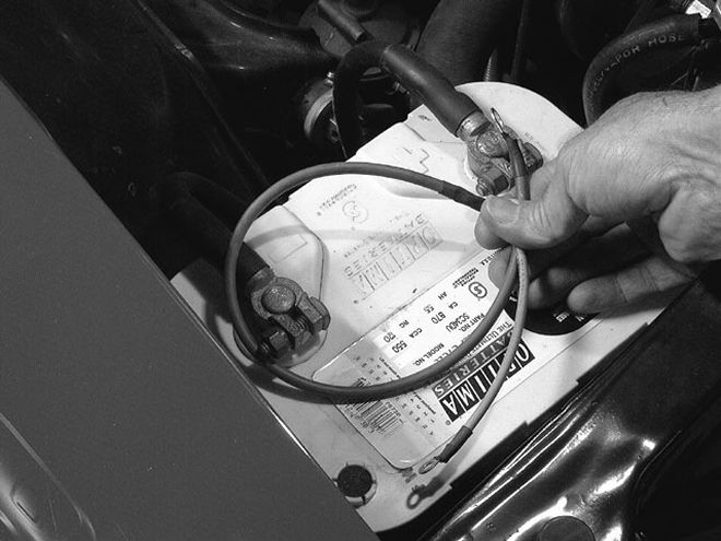
 All GM cars from the '60s and early '70s use this separate 12-volt lead from the positive battery terminal to feed electrical power to the entire car separate from the starting circuit. This 14-gauge wire is way too small to adequately feed the electrical demands of the rest of the car. The small wire means high resistance. We changed to a large 8-gauge wire along with a fusible link, and all the electrical components' performance improved immediately.
All electrical devices require dozens of feet of stranded wire and connectors to make all this happen. While voltage loss is proportional to increases in wire length, the big voltage-drop culprits are connections. This is especially true with poor connectors or hastily performed temporary fixes that become permanent repairs. A poor connector or a power feed line that has been spliced several times can quickly become a focal point for many electrical problems. There are several ways to make a good electrical connection, but we'll go over just one. The key is to make the connection as permanent as possible in order to prevent problems from occurring later.
The best way to create an excellent electrical connection is to use quality terminals instead of those cheesy plastic-coated connectors. Stick with the standard non-insulated connectors. Use a quality wiring stripper and crimping tool, and if you're really motivated, you can also solder the connection to ensure minimal voltage loss. With that done, you can finish the connection by covering it with a length of shrink tubing.
Most musclecars can benefit from a live 12-volt power source under the hood near the battery. If you've ever seen a positive battery terminal with six or eight different wires leading off the terminal, you know that it's less than attractive, let alone barely functional. The much cleaner alternative is to mount a terminal near the battery that is fed from a large 8-gauge wire from the battery. This terminal can then feed high-current items like an MSD-6 box, stereo amplifiers, nitrous solenoids, and electric fans.
Adding Circuits
Another difficulty facing car crafters that wish to upgrade their older supercars is that there are usually very few extra electrical circuits in these older cars that offer fusible circuit protection. Adding extra circuits on an as-needed basis is clumsy. A much more expedient method is to employ one of those add-on circuit boxes available from companies like Painless. These are pre-wired circuit boxes with built-in ATO-style fuses that can manage several circuits without overloading your existing fuse box. The biggest hassle would be finding a place to mount the box. Then all you have to do is wire up the circuits you want to add and you're ready to run. Painless offers these slick units in universal 3-, 7-, and 12-circuit blocks complete with fuses and a heavy-duty relay. Painless even offers a 12-circuit universal pre-wired fuse block that will replace your existing fuse box. These kits are very easy to install and will give a professional look to your wiring system.
Like most things in life, it's the little things that can trip you up and make you miserable. Eliminating those pesky electrical gremlins is about knowing how to do the job right the first time. Apply a little bit of electrical savvy to your next wiring job, and you won't have to pay the consequences of being stranded alongside the road with a melted harness.
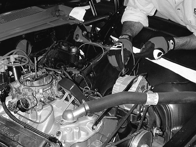
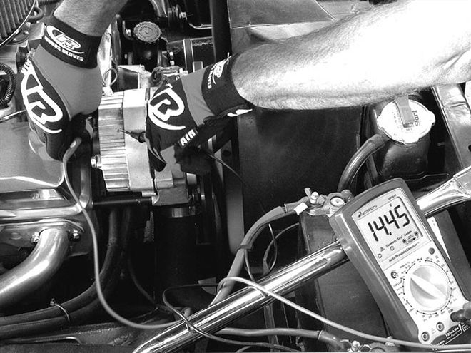 The simplest voltage-drop test is to compare the voltage at the back of the alternator to the voltage at the battery posts. The ideal voltage difference should be no more than 0.4 to 0.5 volt. On this Camaro, we measured 14.4 volts at the back of the alternator and a mere 13.5 volts at the battery, which means this Camaro is losing 0.9 volts between the alternator and the battery--about twice the acceptable limit.
Drop It
One of the most valuable and easy tests you can run on any electrical circuit is a voltage-drop test. All you need is a digital voltmeter and a little bit of time. The voltage-drop test measures the amount of voltage that is lost in the circuit due to high-resistance connections, bad cables, weak switches, or a poorly functioning component.
The simplest test is to measure the amount of voltage drop that occurs between the alternator and the battery. Start the engine, and using your digital voltmeter, measure the voltage at the back of the alternator by placing the red lead on the alternator output terminal and the black lead on the alternator case for a ground. Then measure the voltage at the battery with the red lead on the positive and the black lead on the negative battery terminal. On our test Camaro, the alternator cranked out 14.4 volts, but the reading at the battery was only 13.5. This meant there was a 0.9-volt drop between the alternator and the battery. An acceptable voltage drop is more like 0.4 to 0.5 volt. We either have a wire with high resistance or a bad connection. We've seen as much as a 1.5-volt drop on an early Chevy musclecar traced to an undersized fusible link.
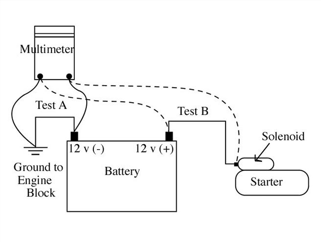 This illustration shows how we tested both the positive and negative battery cables. With the engine cranking, we found a 0.6-volt drop for the ground cable and a massive 1.0-volt drop on the positive cable. By just changing to larger M.A.D. cables, we reduced the starting-circuit voltage drop in half to 0.8 volt total. There are other smaller changes we could have made to improve the circuit even more.
Remember that voltage-drop tests must be performed while the system is operating. Another popular voltage-drop test is with the starter circuit. GM cars are famous for "heat-soak" problems that occur because resistance increases with temperature. Again, the test can only be performed with the starter in operation. This produces a current flow and therefore a voltage in the circuit. To perform our test, we disabled the ignition, set the digital voltmeter on the millivolt (0.001 volt) scale, and tested each series of connections. For example, we tested the voltage drop for the positive battery cable between the solenoid and the positive battery terminal on a '68 Camaro. While the positive battery cable looked fine, we discovered a massive 1-volt drop in this cable alone! In order to record these high readings, we had to switch to the 2-volt scale on our multimeter. Combined with the smallish negative cable, the two cables alone produced a massive 1.6-volt drop in the starting circuit. The owner noted that the car had always had difficulty starting when it was hot. An acceptable level might have been around 0.20 to 0.40 volt for each cable.