Given the number of projects that are under construction in the Source Interlink Tech Center it often comes as a surprise that it’s, for the most part, a one-man show. And while any number of editors can be found there spinning wrenches when they can sneak away from their computers, Jason Scudellari is often the guy installing parts and getting his hands dirty—hence his aliases, Installation Jason or I.J. for short.
While Jason has his hands full with a variety of in-house projects, he does get a chance to work on his own stuff from time to time. His latest undertaking is a 1956 Chevy pickup that is being built with an emphasis on performance, specifically carving corners on the track and at autocross events.
To give the truck a competitive edge the engine has been moved back 6 inches to get more weight to the rear wheels. In addition, a Wilwood swing pedal assembly has been added, which includes three master cylinders, one for the clutch and two for the brakes. The brake master cylinders are operated via a balance bar on the pedal assembly that allows for quick and easy brake bias adjustments—just the thing for getting deep into the corners and shaving a few ticks off the stopwatch.
Relocating the engine, mounting the pedals, and hanging the Flaming River steering column all meant one thing—the truck was going to require a custom firewall. So, during those rare moments without the usual deadline-driven demands on his time, Jason turned his attention to the making the necessary modifications. Too bad the nickname Fabrication Jason doesn't sound quite right.
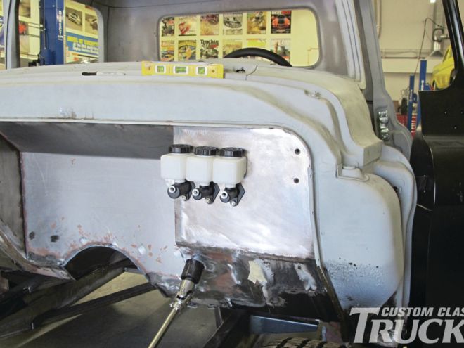
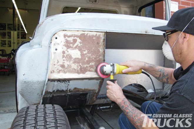
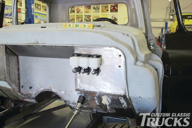 1. Jason Scudellari modified his 1956 Chevy pickup’s firewall to accommodate an LS engine that will be slid back in the chassis, Wilwood master cylinders and swing pedals, and a Flaming River steering column.
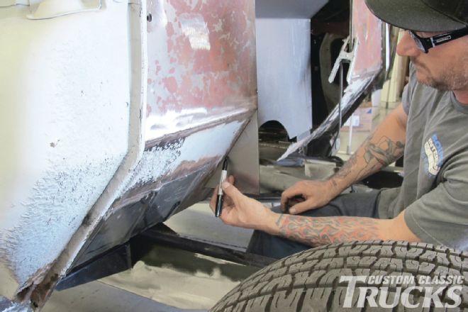
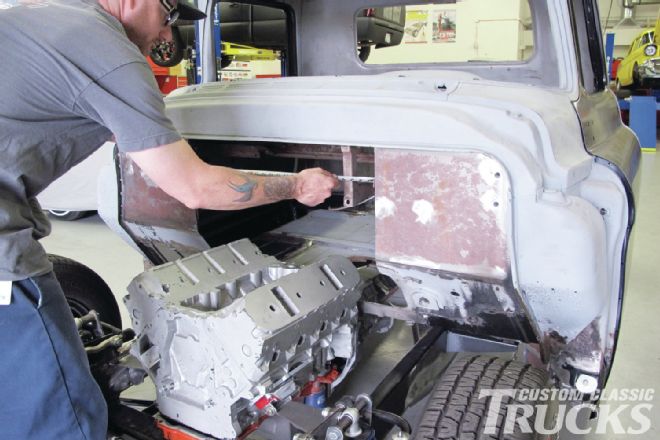 2. As Jason explains it, "Normally they say number two spark plug at the centerline of the wheel is good. The front of my engine is just behind that mark." Here he measures to make the piece to plug the hole in the original firewall.
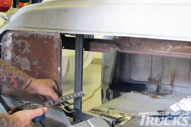 3. To make measuring easier and more accurate, a temporary steel framework that represented the size of the recess was clamped in place.
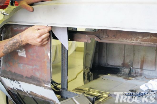 4. The top of the firewall recess will slant down—a pattern was made to determine the proper angle.
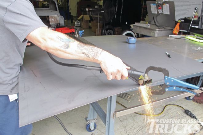 5. Jason fired up the plasma cutter and sliced off a piece of sheetmetal that would be used to form the center of the recess.
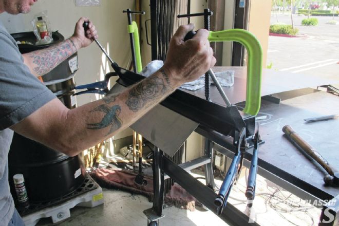 6. Using the pattern made earlier, the top of the recess was bent to the desired angle with an inexpensive brake.
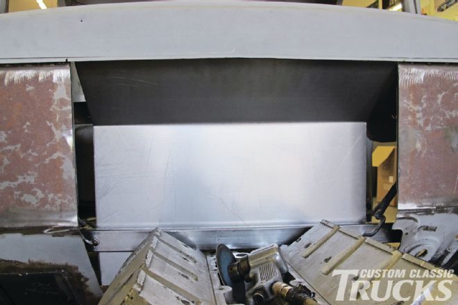 7. To check the fit and alignment of the edges, the filler piece was clamped in place.
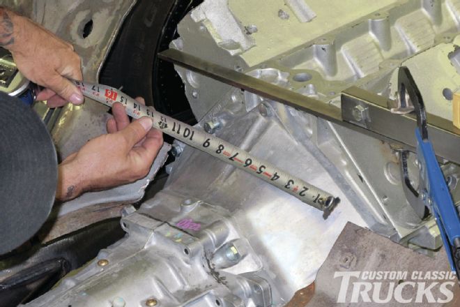 8. The next trick was to determine how big a notch would be necessary. This was established by measuring across and down from a temporary brace to three spots on the transmission.
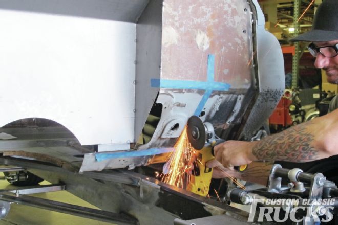
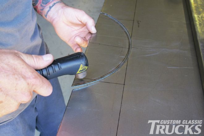 9. With the width and depth measurements transferred to the firewall, the arc of the opening was established then cut with the plasma torch.
 10. After trimming, the center portion of the recess was clamped to the temporary framework to double check the fit.
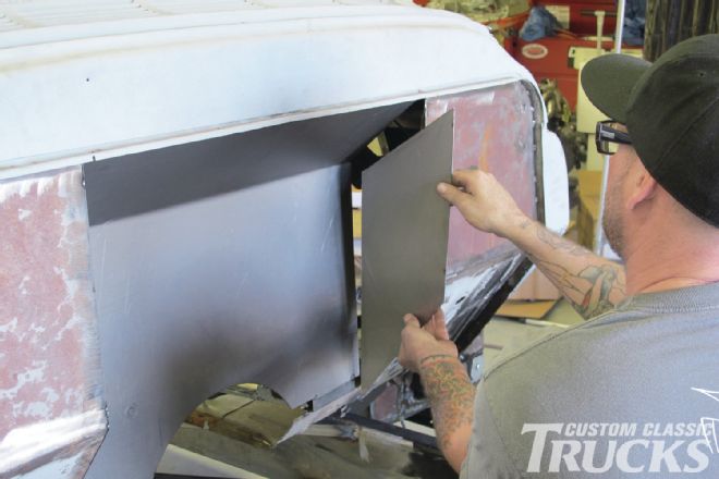 11. Satisfied with the center section, Jason cut panels to fill in the sides of the recess.
 12. The panels were held in place then marked for trimming.
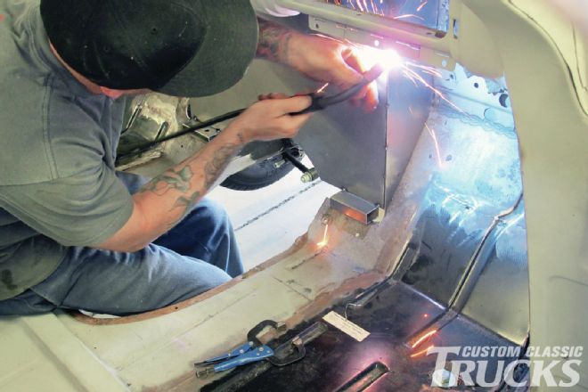 13. Cut down to size, the side panels were tack welded to the recess and the original firewall.
 14. Dealing with the holes in the toeboard for the original pedals, steering column and trans tunnel came next. The entire area was simply cut away.
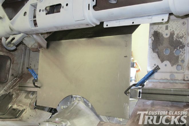
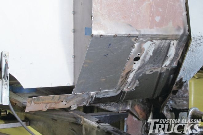 15. A replacement panel, without all the holes, was cut to size and tack welded in place.
 16. After all the replacement panels were completely welded the exposed edges were ground smooth.
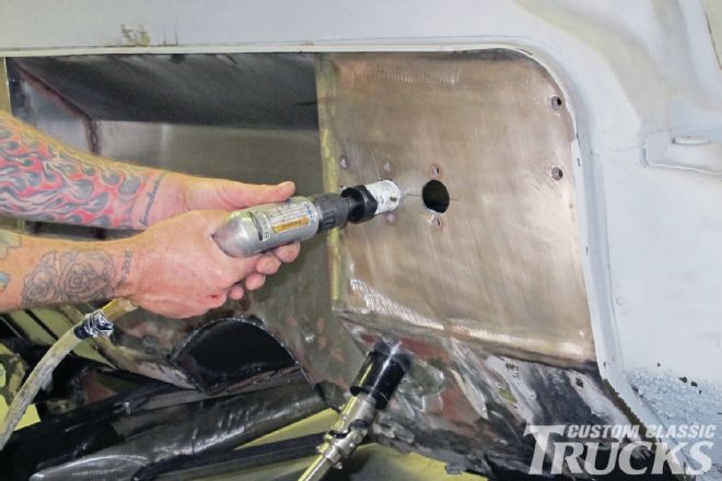 17. A hole saw was used to cut the openings for the trio of Wilwood master cylinders that would be installed.
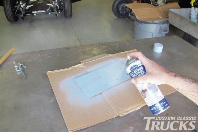 18. To stiffen the area where the swing pedals would mount, a “doubler plate” was made. It was coated with Eastwood’s self-etching weld-through primer before installation.
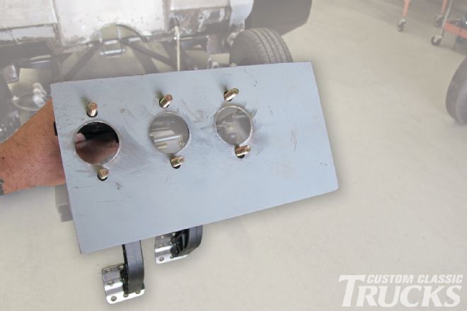 19. Here the reinforcement plate has been attached to the Wilwood pedal assembly.
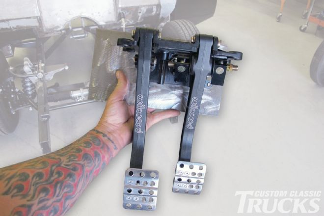 20. Wilwood’s trick pedal assembly operates the clutch master cylinder and has a balance bar to allow fine-tuning of the brakes front to rear. In addition, with two independent hydraulic systems, should one brake master cylinder fail, the other system may remain functional.
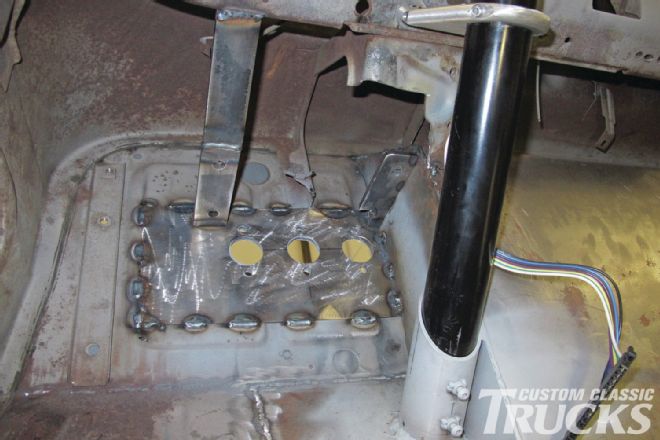 21. To support the pedal assembly a pair of additional mounts were added. Note how the Flaming River steering column attaches to the dash with a swing mount and slips into a tubing mount welded to the toeboard.
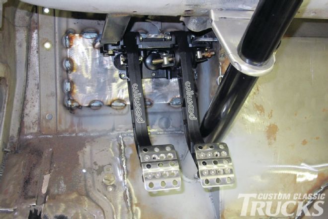 22. With the reinforcement stitch welded to the firewall, the pedal assembly bolted through the firewall and to the added brackets and the steering column triangulation, this is one solid pedal assembly.
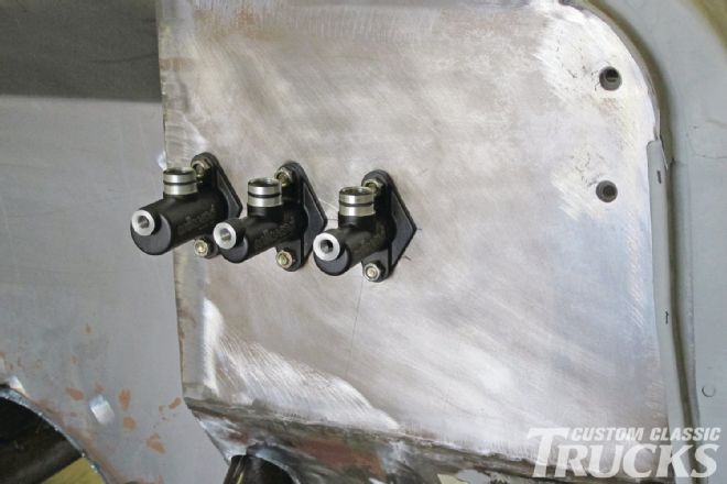 23. The master cylinders are bolted to the pedal assembly, sandwiching the firewall in the process. We’ll show how the balance bar operates in a future installment.
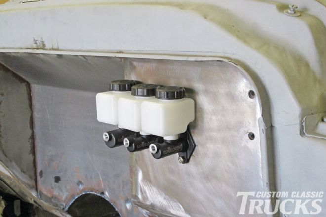 24. Wilwood’s reservoirs simply snap in place. Various size reservoirs are available, as well as remote fill designs for under-floor master cylinders.