
Last issue we covered the basic purpose of a turbo system’s wastegate, as well as taking an in-depth look at the design and manufacturing challenges associated with producing top-quality wastegates with the help of Turbosmart USA’s General Manager Marty Staggs. Marty’s back again this issue to help shed some much-needed light on the external versus internal wastegate debate, as well as to offer some expert advice on how best to size and position external gates on a custom turbo setup.
As we discussed last issue, a wastegate provides a mechanical means of controlling boost pressure by diverting exhaust gas flow to the turbo’s turbine once the desired boost level is reached. The wastegate therefore prevents over-revving the turbo and over-boosting the engine. Sounds simple enough, but as Marty explained, wastegates must be able to function flawlessly in a superheated environment, often well over 1,000 degrees F. Should the diaphragm rupture or spring fail, your engine’s going to experience a world of hurt.
 |
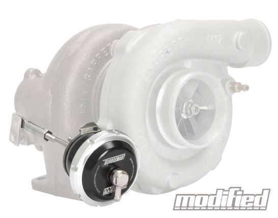
A high-quality internal wastegate actuator improves boost response, even on a stock turbo, but if the flapper valve won’t flow enough for your desired power level, it’s time to go external.
|
A high-quality internal wastegate actuator improves boost response, even on a stock turbo, but if the flapper valve won’t flow enough for your desired power level, it’s time to go external.
When corresponding with Marty about wastegates, one of the first questions that came to mind was positioning of the gate(s) within the turbocharger system. OEMs tend to go with turbochargers that use an internal wastegate, while most aftermarket turbo kits use an external wastegate. Internal wastegates are built right into the turbocharger’s turbine housing and consists of a flapper valve, a crank arm, a rod end, and a pneumatic actuator. Inside the actuator there’s a diaphragm and a spring, and once boost pressure overcomes the spring, it opens the valve and controls boost in much the same way an external wastegate does. However, the actuator is connected strictly to boost pressure, so unlike an external gate it is not linked to vacuum from the intake manifold.
OEMs tend to prefer an internal wastegate approach, since it offers smaller overall packaging, reduces manufacturing costs, and internal wastegates are, of course, matched to the size of the turbocharger and the desired boost pressure level and overall engine output. So at factory boost levels or slight increases in boost, internal gates can work very well, but when you start to turn up the boost, the limitations of their design start to create problems.
Given that internal wastegates are integrated into the turbine housing, they are, by necessity, quite compact, and this means both the inlet and flapper valve are small. This limits overall exhaust gas flow through the gate, which can cause boost creep at high rpm, and the compact size of the valve means it can be slow to respond to pressure change. As a result, there can be a boost spike when the turbo first spools up, especially if you’ve turned boost up past the OEM level (using a boost controller). You can also get boost level oscillation with an internal gate that’s being pushed beyond its original design parameters.
 |
Notice the nearly symmetrical split of the primary tube to the turbine and the slightly smaller-diameter tube to the wastegate. This is an ideal mounting position that ensures maximum wastegate performance.
|
Notice the nearly symmetrical split of the primary tube to the turbine and the slightly smaller-diameter tube to the wastegate. This is an ideal mounting position that ensures maximum wastegate performance.
Of course there are aftermarket solutions to these limitations, including adjustable actuators, larger dual port actuators, and split downpipes that separate exhaust gas flow from the wastegate and turbine, thereby preventing any mixing of these gas streams, which can cause a buildup of backpressure. Turbosmart’s internal wastegate actuators, for example, feature a wide variety of spring ratings (between 3 and 26 psi) and also feature a collar locking system that allows for fast and reliable spring changes. And just like their external gates, Turbosmart’s IWG actuators are made from high-quality materials that can withstand high stresses and temperatures for prolonged periods of time.
Once you’ve outgrown the factory internally gated turbo and upgraded to a bigger turbo with no wastegate, you will, of course, have to add an external wastegate to your setup. And that’s all right, because there are a number of advantages to external wastegates, chief among them the freedom to size them for whatever boost level you’ve targeted and for the larger turbo and freer-flowing aftermarket exhaust manifold you’ve bolted up.
As Marty from Turbosmart explained, “When choosing the proper size of wastegate, here are some general rules of thumb to go by: A big turbo run at low boost requires a big wastegate, while a big turbo run at high boost actually needs a smaller wastegate. A small turbo run at high boost also needs a small wastegate, while a small turbo run at low boost needs a bigger wastegate. That said, the engine configuration will play a significant role in deciding what size wastegate to use, and there are a few applications that require larger gates simply due to their design and exhaust flow. Honda S2000 turbo conversions, for example, are quite popular, and due to the design of the F-series motor and its high rpm capabilities, we always recommend a minimum of a 45mm wastegate. Rotary engines generate a tremendous amount of exhaust energy and heat, so for those applications, the Progate 50mm and Powergate 60mm are what we would recommend until you go past the 30-plus-psi boost range, at which point you can scale back down to a 45mm (or pair of 40-45mm gates) and still maintain control.”
In terms of installing an external wastegate in the best possible position, Marty had this to say: “Wastegate mounting is very important in order to maximize the flow and control capability of the wastegate. The mounting position of your wastegate is largely determined by your turbo and manifold setup and may be constrained by space restrictions in your engine bay. But with “proper” mounting [that optimizes gas flow to the gate], smaller gates will often get the job done at a lower price. Many times, the mounting of the wastegate is the last thing people tackle and space constraints then force the need for a larger gate due to the less-than-ideal mounting positions.”
 |
External Wastegate Positioning - Getting Wasted: Part 2
|
External Wastegate Positioning - Getting Wasted: Part 2
As I explained last issue, Turbosmart’s engineers have spent countless hours designing their wastegates for maximum performance within the most compact housings possible, so buying a well-engineered wastegate can certainly help overcome any positioning compromises that may occur due to engine bay space constraints. Nevertheless, you always want to optimize the installed position of your wastegate as much as possible.
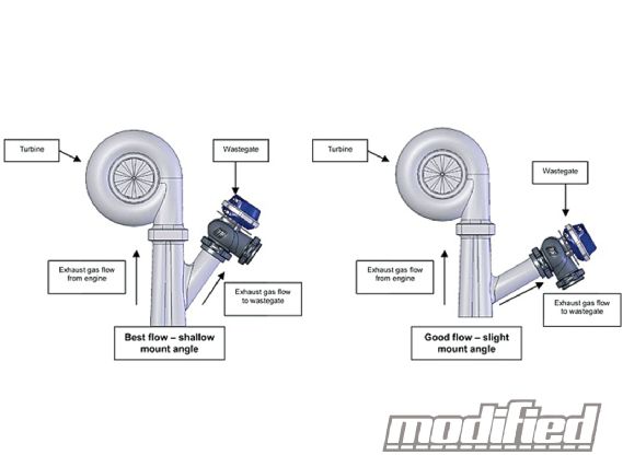
The ideal position for maximum flow to the wastegate is to have its inlet tube mounted at as shallow an angle (more than 90 degrees) as possible from the primary exhaust tubes that feed the turbine. This shallow angle mounting is sometimes referred to as “teardrop” mounting, since a shallow angle cut creates a teardrop shaped where the tube is welded to the primary. A divided or symmetrical setup, where the primary splits exhaust gas flow down the middle between the wastegate and turbine is also a highly efficient design, often seen on pro drag cars. But because of the space constraints normally associated with a street car engine bay, it’s far more typical to see a smaller-diameter tube feeding the gate at a shallow “teardrop” angle so gas flow is still as smooth and uninterrupted as possible.
 |
Tech Talk Wastegate
|
Tech Talk Wastegate
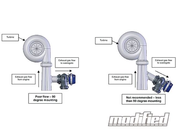
Mounting the wastegate tube at a 90-degree angle is less than ideal, since exhaust gas flow doesn’t follow a natural path to the gate. In some cases this can even cause overboosting, because the gate isn’t seeing sufficient gas flow as compared with the turbine. Worst still is to have the wastegate tube mounted at less than 90 degrees, since this creates poor exhaust gas flow.
 | Tech Talk Diagram 2
Turbosmart’s diagram for external wastegate mounting positions is about as clear and simple a way to visualize your options (from best to worst) as possible.
 |
Tech Talk Diagram 1
|
Tech Talk Diagram 1