 | Restructuring The Physics Of Front Drive - Project Integra, Part VI
In the last installment of Project Integra (December 1999, Part V), we took you through the Body Pros paint process where Derek Teklak worked his magic to get the Acura up to show specs. Along with the paint job, we also highlighted the curb weight issue and addressed it by removing all the unnecessary parts and cutting into the sheetmetal. In this phase of Project Integra, we will be constructing the roll cage and unveiling a few of our suspension tricks. Technical Editor Gary Castillo is heading the project and for the most part designing and fabricating the entire chassis and suspension components himself with the help of Richard Green from Rells Peformance Motorsports' in Chula Vista, Calif. Competition Engineering of Guilford, Conn. is supplying the majority of the suspension components as we complete Project Integra's transformation from street cruiser to strip bruiser.
Because there are no formally established rules for import drag racing, we had to look into the NHRA rulebook for guidance before constructing the roll cage. Of course, the three major sanctioning bodies for import drag racing (IDRA, IDRC and the NIRA) have basic rules that level the playing field; however, they do not have rules which regulate the build-up of a front-drive drag car.
Ultimately the goal for Project Integra is to break into the single digits, so we had to make sure the Integra was built to NHRA specs. The NHRA rulebook states that any car running 10.99 or quicker must have a roll cage. For the complete ruling on roll cages check out the accompanying chart on page 50. Since curb weight is a major concern, we decided to construct the cage and suspension components out of super-light 4130 chrome-moly.
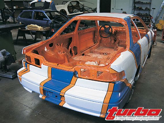
We elected to go with a bare-minimum roll cage and not one with useless cross bars that only add weight. Unlike most roll cages, our cage actually goes through the unibody and attaches to both the front and rear suspension through the rear shock towers and the firewall. The entire suspension and roll cage are tied together and built around the unibody.
The entire OEM suspension has been removed in order for us to reconstruct a custom suspension, which does not utilize the factory mounting points-shock towers and lower control arms. Keep in mind that the only thing stock on Project Integra will be the unibody. In a later installment we will unveil the suspension because it is still in the developmental stage and we haven't decided on the final design. The basic premise of the custom suspension is to transform the weight transfer properties generated by the car's front-wheel- drive configuration into something positive.
As of now, all the theories on our suspension design have yet to be proven, but we are determined to rewrite the books on front-drive traction. This is our goal; only track time will tell us if we're on to something or not. Stay tuned as we go forward with our suspension tricks in future installments of Project Integra.
NHRA Rulebook Section 4:11Roll CageAll cage structures must be designed in an attempt to protect the driver from any angle, 360 degrees. All 4130 chrome-moly tube welding must be done by approved TIG-heliarc process; mild-steel tube welding must be approved MIG wire feed or TIG-heliarc process. Welding must be free of slag and porosity. Any grinding of the welds is prohibited. Additionally, the roll cage must be padded anywhere the driver's helmet may contact it while the driver is in the driving position.
Full-Bodied CarsOn full-bodied cars, with the driver in driving position, the driver's helmet must be in front of main hoop. If the helmet is behind or under main hoop, additional tubing the same size and thickness as the roll cage must be added to protect the driver. Main hoop may be laid back or forward, but the driver must be encapsulated within the required roll cage components. On unibody cars with stock floor and firewall (wheeltubs permitting) the roll cage may be bolted or welded to the floor/rocker box via 6x6x.125-inch steel plates.
All cage structures must have in their construction a cross bar for seat bracing and as the shoulder harness attachment point; cross bar must be installed no more than four-inches below, and not above, the driver's shoulders, or to side bar. All required rear braces must be installed at a minimum angle of 30 degrees from vertical and must be welded in. Side bar must pass the driver at a point mid-way between the shoulder and elbow.
Unless an OEM framerail is located below and outside of driver's legs a rocker or sill bar, minimum 1-5/8x.083-inch CM or .118 MS or 2x2x.058-inch CM or MS retangular, is mandatory in any car with a modified floor or rocker box within the roll cage uprights (excluding six-square feet of transmission maintenance opening). Rocker bar must be installed below and outside of driver's legs and must tie into the main hoop, the forward hoop, frame, frame extension or side diagonal. Rocker bar may not tie into swing-out side bar support. If rocker bar ties into the side diagonal more than five-inches (edge to edge) from the forward roll cage support or main hoop a 1-5/8x.083-inch CM or .118 MS brace/gusset is mandatory between the diagonal and forward roll cage support or main hoop.
Swing-out side bar permitted on OEM full-bodied car running 7.50 e.t.s and slower. The following requirements (a through d) will be enforced on all cars.
a. 1-5/8-inch O.D. x .083 (CM) or .118 (MS) minimum. Bolts/pins must be 3/8-inch diameter steel, minimum and in double shear at both ends.
b. Male or female clevis(es) permitted. Male clevis must use two minimum 1/8-inch thick brackets (CM or MS) welded to each roll cage upright; female must use minimum 1/4-inch thick bracket (CM or MS) welded to each roll cage upright. Pins must be within eight-inches of the vertical portion of both the forward and main hoops. A half-cup backing device must be welded to the vertical portion of the main hoop (inward side) or the upper end of the swing-out bar (outward side), minimum .118-inch wall (CM or MS) extending at least 1-5/8-inch past the center of the pins. A clevis assembly using a minimum .350-inch thick male component and two minimum .175-inch thick female components may use a 1/2-inch diameter Grade 5 bolt and does not require a half-cup backing device.
c. Sliding sleeves of 1-3/8x.083-inch CM or .118-inch MS with minimum two-inch engagement are permitted in lieu of the upper pin/cup.
d. All bolt/pin holes in the swing-out bar must have at least one hole diameter of material around the outside of the hole.
If the OEM firewall has been modified (in excess of one square foot for transmission removal not including bolted in components) a lower windshield or dash bar of 1-1/4x.058-inch 4130 chrome-moly or 1-1/4x.118-inch mild steel is mandatory to connect the forward cage supports.