 | Seat Time
The internal combustion engine lives by some pretty basic principles, some of which include letting air in, compressing said air, and letting air out. An engine's valves come into play during each of these three processes and determine the engine's overall degree of success. How well the valves perform, or how well an engine inhales, compresses and exhales, is determined by many factors, one of which is the valve job.
For any valve to work optimally, it has to be able to open as far as possible, as fast as possible, close just as fast, and provide a perfect seal. And you don't have to necessarily be talking about your car's engine for that to hold true. While valvetrain components like camshafts, valve springs and rocker arms do affect valve speed and timing, it's the cut of the valve face and its corresponding seat on the cylinder head that determine how well it'll seal and how well air will ultimately flow past it. You see, a valve spends most of its running life - when it's not closed - in a low and partial-lift situation. For every time a valve reaches full lift, you'll find it positioned at partial and low-lift twice. After all, it's gotta come up and it's gotta come down. As such, you can see the importance of doing everything possible to increase airflow past the valve, and not just ensuring that it seals properly. You may already be aware that flow decreases whenever its direction is changed because it loses its orderly nature, so it's important to minimize its direction change as much as possible when transitioning through the ports. A properly performed valve job will increase engine performance at all RPM levels since flow can potentially be increased at all levels of valve lift through smooth transitioning. And, for the gas-tight seal an engine needs when the valves are closed, there's no room for error when it comes to these clearances. It's arguable that the valve job is the most important element to a well-flowing head, as the cut of the valve face and seat together determine the shape airflow will ultimately take past the valve.
Last month we introduced you to Project Laser, bent valves and all. Since then, we've had a chance to remove and disassemble the cylinder head and find out what's really going on in there. As we suspected from our leak-down test results, most of the 4G63T's valves were bent. We knew they would be. After all, broken timing belts and interference engines rarely produce happy outcomes. Lucky for us though, the Mitsu's pistons were able to absorb the valves' impact with little indication of the whole mishap.
Some might accuse us of going about this whole Diamond Star buildup the wrong way. With the head off, most agree now is the perfect time to install some oversized, stainless valves, send it out for some porting, maybe even stuff in a set of high-lift camshafts. It's difficult to argue with this approach, at least from a labor standpoint. Why remove the head and valvetrain more than once? But as much sense as this makes, that will only leave us without a baseline dyno figure and a somewhat backwards approach to our buildup. Instead, we'd like to see what we can get out of this 2.0L powerplant beginning with the stock-running engine, then bolt-ons and take it from there.
Either way, new valves need to be installed and a valve job has to be performed. We'd also be crazy not to resurface the head while it's at the machine shop. We dropped our top end off at nearby Valley Engine and Machine where it was first hot-tanked and cleaned of its 15-year grease and carbon buildup. Before we dropped off the head though, we checked it for straightness, looked for cracks and measured our valve guide clearances. The machinists at Valley performed a three-angle valve job, which consists of cutting the seats and reconditioning our new/used valves. They also surfaced the head and hot tanked a number of our top-end components for us.
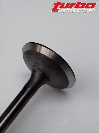
Many lesser production engines receive only a single-angle valve job consisting of a 45-degree valve face and matching seat on the head. These are fairly quick and inexpensive for manufacturers concerned with bottom lines, assembly lines and time constraints, and frankly, they do just enough to get the job done. But, performance-wise, nothing comes close to a multi-angle valve job. There are a few kinds though - three angle, five angle and radius are popular ones. Either way, any valve job consists of seats and faces that must be concentric with one another for a good seal.
The three-angle valve job is the most common and is what we opted for. The cut on the valve face and corresponding valve seat is the same here: 45 degrees (larger valve eight cylinder engines sometimes vary face and seat angles by one degree for an interference fit, but this is fairly uncommon with smaller engines). But two more angles are added to the front and backside of the seat, and they each serve a different purpose. First, a cut is made to allow for a smoother transition between the valve's face and stem area - the port side or back of the seat. This cut is typically around 60 to 70 degrees. A second cut is made where the top of the valve meets the valve's margin - the chamber side or top of the seat. This cut is typically around 20 to 30 degrees and aids in smoothing airflow either into or out of the combustion chamber, depending on whether you're looking at the intake or the exhaust side. Once these cuts are made, the seat's sealing surface in turn becomes narrowed; it's important to note that the angle of both the top and back cut will dictate how wide the seat will be because it's just adjacent to them. The good thing about narrowing the seat though is that sealing pressure is increased here. It also increases airflow past the valve due to the unshrouding effect it has. In other words, not only can more air get past the valves now, but just as importantly, more air can get past the valves sooner. But it's important not to go too narrow as this can sacrifice the durability of the seat itself. A compromise needs to be made. A typical valve seat on a four cylinder engine measures in somewhere between .035 to .055 inches. We can err on the small side of this figure and achieve fairly durable results and maintain the flow we want. One thing to keep in mind here is to cut the exhaust seat slightly larger - around .010 inches or so to allow for better cooling by heat dissipation through the slightly larger contact patch. And for turbocharged engines in which the exhaust valves are subjected to even more heat, it's not a bad idea to increase the width even more.
There's little more to a five-angle valve job than two additional cuts - much like those performed on the three-angle valve job. As you might have guessed, these create an even smoother transition for air to flow past. Adding more cuts creates a rounder seat, which brings us to a radius valve job. There are as many theories as to how many angles work best as there are machinists capable of performing a valve job. We've even heard of and seen four-angle, seven-angle and you-name-it valve jobs, although we think the difference between seven angles and a complete radius is pretty negligible. On a final note, performing a good multi-angle valve job is almost always a good idea, but there is a diminishing point. The more times a valve job is performed, the farther the valve seat sinks into the cylinder head, ultimately decreasing airflow.
Besides reconditioning the valve seats, there's work to be performed on the valves. We mentioned the 45-degree valve face, which seals against the seat, but there's more to it. It's important for the intake valve's margin to meet up sharply with its face, but on the exhaust side, a smooth radius is often desired. Why? Because the air is traveling a different direction here. Generally, an exhaust valve's margin will be slightly larger as well. The 4G63's exhaust margin width is roughly .010 inches larger than the intake's. While a smaller margin is often desirable, it's best not to go too small here, so as to leave room for future reconditioning. Who knew that the valve margin was so important and could determine both flow patterns and reliability. It's also possible to increase flow by cutting an angle on the backside of the valve - somewhere in the neighborhood of 30 degrees or so. This cut, positioned away from the seating surface, further aids in unshrouding, especially at low lift.
With our top-end now taken care of we'll soon be putting our 4G63T back together and strappin' it to the dyno for some baseline testing. Be on the lookout for our initial dyno figures and our first stage of bolt-ons for Project Laser.