| 0109tr Suspension 01 Z
Over the years, technology has developed many innovative and interesting ways to suspend a truck. In the beginning, the truck had inherited its suspension from the buckboard wagon and stagecoach, using straight axles at both the front and rear, which were both suspended by leaf springs. The number of stacked leaves would determine the leaf spring pack's strength. This type of suspension proved to be rigid and firm, with not much softening or absorption of the terrain or surface imperfections, making for an uncomfortable and sometimes violent ride.
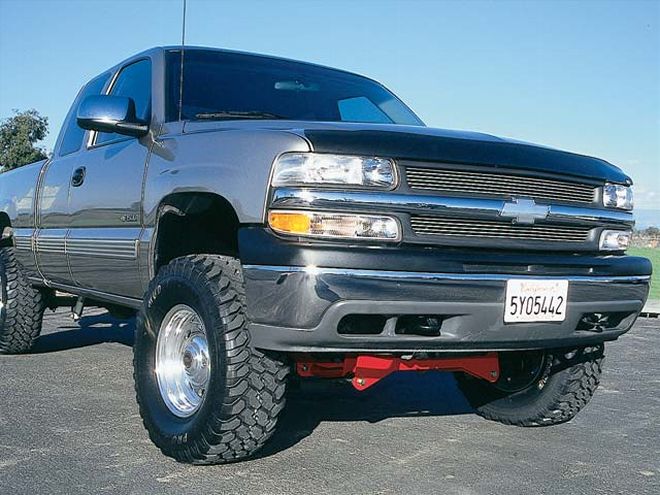
| chevrolet Hd Pickup front Left View
The objective of any suspension system is to reduce and control the energy of the up and down motion conducted by a vehicle's acceleration, braking, and cornering. During motion, the suspension system is designed to control the vertical energy transmitted by changes in the road surface or off-road terrain. To control and reduce these actions will help eliminate driver fatigue and reduce cargo damage. The other major objective of a suspension system is to keep the wheels and tires of the vehicle in constant contact with the road or terrain surface, maintaining the truck's control. The wheels and tires may lose contact with the road surface due to imperfections in its surface, which will cause vertical oscillation (up and down motion). Without suspending the vehicle separately from the frame, the vehicle would be absorbing the oscillating energy, causing the entire vehicle to accelerate this energy vertically, losing contact with the ground surface. This parabolic action will depend on the acceleration speed of the vehicle, the size of the convex (bump) or concave (pothole) irregularities of the terrain and the mass weight of the vehicle.
By introducing a means of suspension, the vehicle will maintain the wheel and tire contact with the ground surface by artificially increasing the mass weight of the vehicle by means of springs. Due to the fact that a spring under compression will try to resist this action by pushing back down on the axle plane, the greater the compression action, the greater the force of the spring that will apply in its reaction of energy. For every action, there is a reaction. The stiffness of the spring will dictate the speed of the spring. The stiffer the spring, the quicker its reaction time is, the softer the spring, the slower its reaction time is. The stiffness will also determine the travel of the spring because a quicker spring travels less than a slower spring. Suspension is a continuous, controlled action of vertical energy.
If a suspension system was comprised of only springs attached to axles, as the vertical energy would increase, its oscillation would resonate to a more rapid frequency due to the amplitude of the oscillation. The suspension system is made up of three major components, the load or sprung weight, springs (leaf and coil springs), dampers (shock absorbers), and unsprung weight (spindles and axles). The greater the unsprung mass, the less sensitive to displacement caused by the terrain irregularities, and once the vertical motion begins, it will accelerate energy and continue to do so due to the inertia factor. Another unsprung mass phenomenon is that the amplitude of wheel and tire hop becomes greater for less massive unsprung mass, meaning the wheel and tire are in contact with the ground less, and handling is adversely affected.
Types of SpringsThere are three types of springs that have been used during the evolution of suspension systems. They are coil springs, leaf springs, and torsion bar.
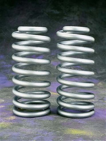
| A coil spring is a continuous spiral wire that is coiled to achieve its progressive strength. The wire diameter and tightness of the coils will dictate the spring rate and strength, while the overall length will determine the ride height.
Coil SpringsA coil spring is constructed from round bar stock wire that is wound or coiled either by a hot or cold procedure. Cold wound springs are formed by an ambient temperature winding method: A spring winding machine extrudes the wire in a spiral action and then is cut to length. The spring is then heat tempered in a furnace, shot-peened, end-ground, preset for fatigue resistance, phosphate treated, and finally powdercoated for corrosive protection. The thickness of the round bar stock and the amount of coils will determine its strength and rigidity of the coil spring.
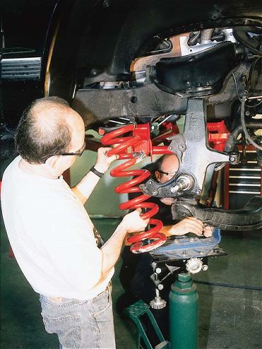
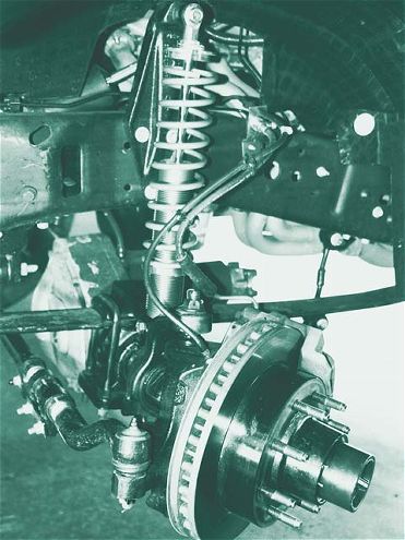
| Most coil springs are located between the front upper and lower control arms. The weight of the vehicle will compress the spring inside the spring pockets. The shock absorber (damper) is usually located inside the coil spring.
The coil winding is another important portion of the overall performance of the spring. The distance between coils will determine the spring rate. A progressive coil spring will have a shorter distance and tighter wind at the beginning of the spring. This is known as the transition portion that controls the static load, then, as the load increases into the active load and progressively becomes greater, the spring compresses and it becomes stiffer.
Referring to the spring load, we are talking about the amount of weight that will compress the spring to a specific height, which is translated into pounds. Spring rate is the amount of weight applied to the spring to compress it 1 inch, which is expressed in inch-pounds. When figuring these principals, we must remember the spring rate will not change during the spring's compression, but the spring load will change. Many times, we see cut coils from a spring as a method of lowering a truck's ride height, but cutting the coils will also affect the ride quality and coil action, increasing the spring frequency, in turn, causing the action to be choppy and bone-jarring.
The progressive action of a coil spring becomes more prevalent as it is compressed. By cutting one coil, the spring will eliminate its less progressive action or a smooth transition, creating quicker spring. This characteristic is demonstrated when we see a lowered vehicle traveling down the road. As it rolls across the highway, its suspension strips, making it oscillate to a choppy, bouncy ride, giving the driver and passengers blurred vision.
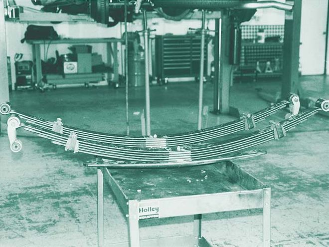
| A leaf spring's strength is determined by its length width, thickness, and severity of the arch. The greater the amount of leaves, the stronger it will be. Notice the main leaf spring rolled eyes at each end of the spring; the rear eye will have a shackle, which will pivot forward and backward. This will allow the leaf spring pack to flex during vertical suspension travel. As the leaf spring flattens out, it increases the distance between the front and rear leaf spring eyes under compression travel. As the leaf spring arch becomes greater, the distance between the front and rear becomes less (bowing).
Leaf SpringThe leaf spring was the first spring to be used with axles and wheels. They were fabricated by blacksmiths during the 1800s who would heat and bend a thin strip of mild steel into a semi-ellipse, or an arch. The length, width, thickness, and severity of the arch are all physical factors, which affect the spring's rate or strength. The width of the spring will affect the rate, and the leaf spring thickness and length have a greater affect on the stiffness of the pack. The arch of the leaf spring creates added strength and recoil action. The spring leaf is drawn and rolled or tapered, which provides flexibility and a smoother ride. Eyes are formed at each end of the main (bottom) leaf spring, then a hole is punched for the stacking (locating) pin.
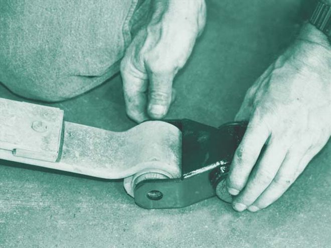
| The rear main leaf spring eye is attached to the vehicle's frame by a shackle that pivots to allow for the springs to move (contract and expand) during suspension travel. As the suspension moves upward (compresses), the leaf spring's arch will flatten the pivotal shackle, allowing the distance between the eyes to increase. As the suspension moves downward (extends), the leaf spring's arch will cup the pivotal shackle, allowing them to move.
The leaf spring is now ready for formation and heat treatment. This process heats the leaf spring in a thermostat-controlled furnace and then forms to the proper free arch, ensuring a permanent arch to the spring. Then it is quenched in a hot oil bath and the leaf is Brinelled (hardness tested). To multiply the spring rate or strength, leaf springs are stacked, which creates a spring pack. A thick spring pack with many thin leaves will conduct a softer rate than one with fewer leaves of greater thickness. The leaf spring packs are clamped together. The mono spring or spring packs are hung from the framerail by shackles (hangers), which allow the springs to flatten out during weight increase or load; the shackles would move or pivot, allowing them to absorb the weight increase. The closer the shackle is to a vertical angle, the higher the effective spring rate. When the shackle is laid back at an angle, it actually becomes a moving link with the spring, and the spring ride will feel softer.
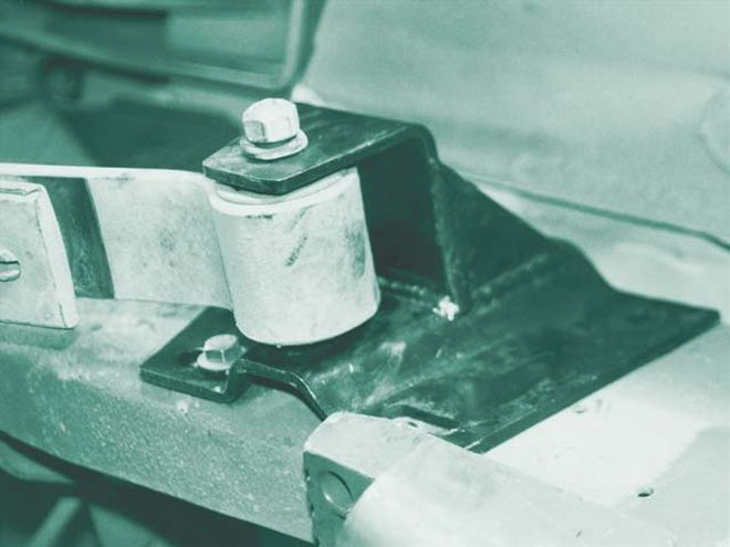
| The front main leaf spring eye is held stationary, only moving in the bushing.
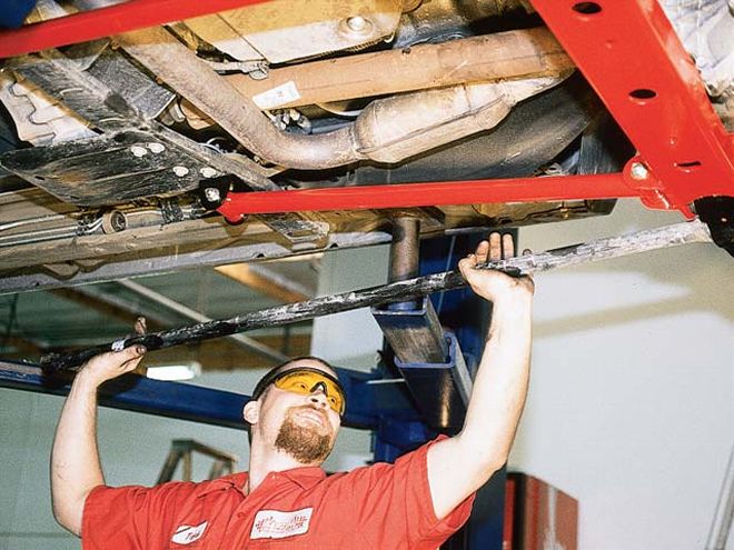
During static load, spring leaf packs have friction between the leaves, causing the springs to ride rough over small bumps because the spring must overcome the pack friction before it starts to flex. For example, rolling slowly over a speed bump, at the bottom of the speed bump, the suspension is rigid with really no feel of suspension absorbing any of the impact. A leaf spring or springs are connected to the axle using U-bolts and plates sandwiching the axle between the two.
| A torsion bar is a straight spring that is splined or brouched on the ends. Used in different applications, a torsion bar is installed into a front suspension of a four-wheel-drive vehicle. The torsion bar ends are locked into a female splined or brouched pocket, and one end is stationary, while the other is allowed to rotate with the motion of a lower control arm. The torsion bar's twisting action is similar to ringing out a towel; both ends twist in opposite directions.
Torsion BarAnother strength-contributing component to a truck suspension system is a torsion bar. These pieces of round bar are cut to specific lengths. The diameter and length will determine its strength. Torsion bars are brouched or splined at both ends; one end is fixed in a pocket in the chassis, usually a crossmember. The other end is fixed to a brouched pocket in the lower control arm. As the lower control travels in a vertical motion, it begins to twist the bar, the fixed ends of the torsion bar are giving each end resistance against one another. The resistance is increased the higher the lower control arm is twisted. Similar to anything else that is under continuous tension and motion, such as a torsion bar, it will weaken over a period of time and have to be readjusted or replaced.
| 0109tr Suspension 12 Z
Dampers (Shock Absorbers)A suspension system with only springs to absorb and suspend the truck's vertical travel would find itself out of control. The purpose of shock absorbers is to control the compression, extension, and frequency of the truck's suspension. A suspension must have balanced suspension shock absorbers to fine-tune the system. The coil springs and leaf springs support the vehicle's weight while the shock absorbers control the velocity of the spring action. Besides damping the initial shock of either a spring's compression, the extension of the shock absorber will damp or decrease the amount of vibrations by absorbing the wheel and tire impacts on the road and terrain imperfections.
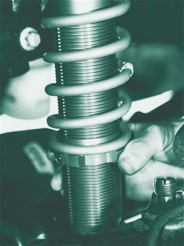
| A coilover shock is constructed with the coil spring sandwiched between an upper and lower collar. The upper collar is fixed, while the lower collar is adjustable because it is threaded up and down the threaded shock body. By tightening or loosening, the lower collar will determine the coilover shock's firmness and the vehicle's ride height.
A shock absorber will slow down and control the compression and extension frequencies (rapid vertical movement). A basic shock absorber consists of a canister (body), a shaft, and a piston. The piston is connected to the shock shaft. It travels up and down inside the shock body, which is filled with a hydraulic fluid or a mix of hydraulic fluid and gas nitrogen, which helps dissipate heat that builds up due to the friction of the shock's oscillating action. This helps eliminate cavitation (foaming of the hydraulic fluid). With the help of hydraulic action, the shock travel is damped. The amount of time it takes a shock to go back to its normal or static ride height is referred to as rebound. By controlling each wheel and tire, vertical travel frequencies will keep the truck's overall suspension under control.
As a truck's suspension is lowered, the amount of travel within the shock absorber is also decreased. The internal design of a lowered truck shock is different than that of a stock ride height shock. Because of the shorter travel, the lowered shock valving is altered. To help control the shock absorber's frequencies, the shock body is filled with a hydraulic fluid (a petroleum-based oil) that is moved through a series of valves while a single piston controls the shock shaft travel.
Types of Shock AbsorbersTwin TubeThe twin tube moves the fluid in and out of two separate chambers that act as reservoirs by opening and closing valves at the bottom of the shock. As pressure is increased by compressing the hydraulic fluid, it forces the fluid through the holes or valve in the shock piston.
Mono TubeThe shock has a single, high-pressure chamber that exchanges the fluid from one side of the piston to the other by means of valves of fluid flexing discs on the piston head itself.
Gas FilledThis is used to pressurize the shock tube with nitrogen gas, which improves its ability to the resistance of compression and extension of the shock's travel. This will improve the shock's ability to control oscillation. Higher gas pressures can eliminate cavitation entirely when used in a mono-tube design.
IAS (Inertia Active System):IAS is new design developed by Edelbrock. The shock is a mono-tube design similar in appearance to the Bilstein shock. These IAS shocks are filled to 280 psi of nitrogen gas to prevent cavitation. The secret is in the valving system, a moving part attached to the piston assembly that is called an inertia valve, which allows the shock to behave according to the type of input it receives. The inertia valve is a heavy piece of bronze that floats above the piston, suspended on springs that balance its weight against gravity.
When the piston or rod moves sharply downward in rebound, the inertia valve tends to stay at rest, floating on top of the piston assembly. The shock is valved normally for compression, but when the piston begins to move downward, powered by the buildup of the spring energy, the inertia valve stays put and then follows the travel of the piston downward, opening the orifices between the valve and piston to allow oil to flow through. It's still metered, but the flow is higher than with the valve closed in the default position. As soon as the tire is planted again on the ground, the valve resumes its normal position and the shock is metered through the piston only. The result is that the tire remains planted on the ground, regardless of the nature of the terrain.
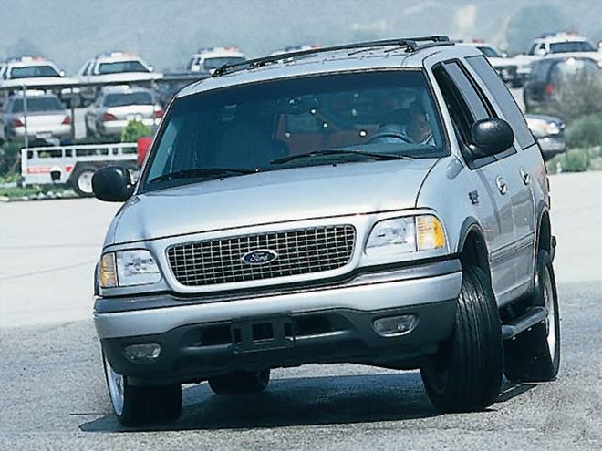
| Sway bars will eliminate and control lateral body roll. The sway bar will torsionally link the front and rear suspension from side to side as the lateral weight is transferred under cornering. When turning to the left, the weight is transferred from the left to the right due to lateral energy and centrifugal force. In the direction of the turn, the inside wheel will become light and the outside wheel will become heavy.
Sway Bar (Antiroll Bar)A sway bar works under the same principal as a torsion bar, resisting energy by introducing energy against energy, (torsional) strength. The purpose of a sway bar is to eliminate body roll during cornering. As a vehicle begins to turn left or right, it is creating lateral energy and weight transfer. In doing so, as a truck turns, the weight transfers to the opposite side when it is turning. If the truck is turning left, the weight is unloading the left side of the chassis and transferring or loading the weight to the right side. As the truck turns to the right, the chassis is being unloaded on the right side and transferring the weight, loading the chassis on the left side. As the weight is transferred from left to right, or right to left, the chassis is loaded and unloaded from side to side. To increase the cornering and handling performance, a sway bar will eliminate the majority of the body roll, contributing to a flatter corner.
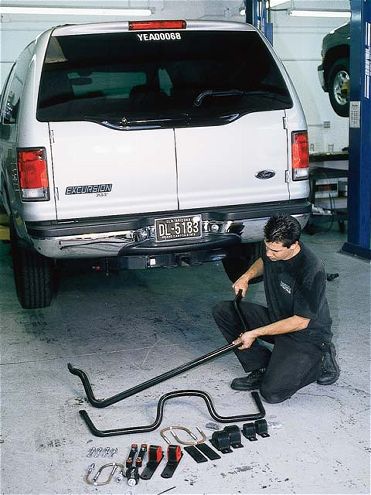
| ford Excursion rear View
A sway bar is U-shaped with flattened ends and holes drilled in them. Sway bar endlinks are used to connect the sway bar to the control arms or axlehousing. The endlinks will transfer the weight from one end to the other by twisting (wrenching) the sway bar arms in opposite directions of one another. Torsion energy is the same action as ringing out a wet towel. The length of the arm from the bend to the end is where the strength comes from. The shorter the sway bar arm length, the stronger; the longer the arm length, the weaker the torsion bar.
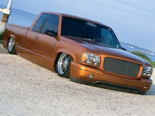
Airbag SuspensionWe have seen many of the traditional lowered 4/6 to 5/7 dropped trucks going to the next level and getting slammed, where you lay the framerails on the ground. This is done with an airbag system.
By removing the factory (front) coil springs and (rear) leaf springs from the truck's original factory suspension, airbags are installed to support the truck and adjust its ride height with the flip of a switch. Using an onboard compressor for its air source and a holding tank for its supply, the solenoids, the valves, and the air lines transport air, pressurizing the airbags, which replace the truck's traditional springs. A four-link system can be installed to keep the rearend located under the frame. Up front, the airbags are sandwiched between the upper and the lower control arms. When purging the air from the front airbags, the geometry will change as the wheel and tire travel upward, following the geometrical arch, tending to tuck themselves inside the front wheelwells. Airbags are located on all four corners of the suspension system. Changing the airbag pressure will adjust the truck's ride height accordingly.
Suspension improvements are made possible by the advanced technology of today's aftermarket manufacturers creating cutting-edge suspension components that will improve a trucks handling and ride height capabilities.