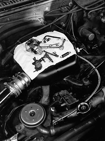
| stanadyne Db2 Injection Pump installation
The diesel industry uses two basic styles of mechanical injection pumps: the inline and rotary. In most applications, the inline pumps are attached to inline engines (due to packaging), while the distributor style can be found on either V-shaped or inline powerplants.
In the '90s, Ford and General Motors required injection pumps for their indirect-injected V-8 diesel engine programs. The injection pumps had to be reliable, easy to service, and most importantly, easily attachable to the engines. When all the available pumps were reviewed, the Stanadyne DB2 (formerly marketed as a Roosa-Master) was both corporations' choice.
To learn more about the DB2 injection pump that was used on the Ford 6.9L and 7.3L, General Motors 5.7L, 6.2L, and 6.5L engines, Diesel Power worked with the University of Northwestern Ohio (UNOH) and staff member Bill Sergent. We also visited with injection pump specialist Brad Anderson, owner of North West Fuel Injection Service in Columbus Grove, Ohio. Anderson is very experienced in repairing, servicing, and hot-rodding the DB2.
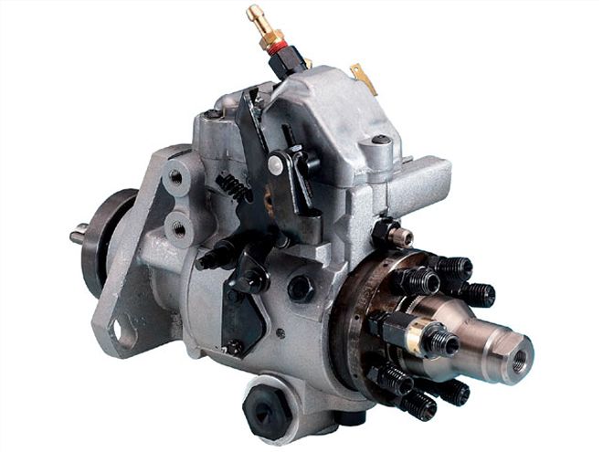
| stanadyne Db2 Injection Pump demo Unit
A diesel engine is different from a conventional gasoline engine in that its cylinders are filled only with air during the intake stroke. Air in a diesel engine is compressed until it reaches extremely high temperatures and pressures, at which point fuel is sprayed into the chamber. Spontaneous combustion occurs as a result of the hot compressed air and the fuel's flash point-the combustion is used to power the downward stroke of the piston.
The fuel injection pump is important because it not only pressurizes the fuel to the mechanical injectors, but provides the required timing advance under all operating conditions.
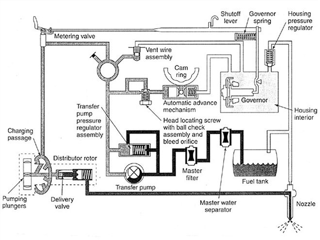
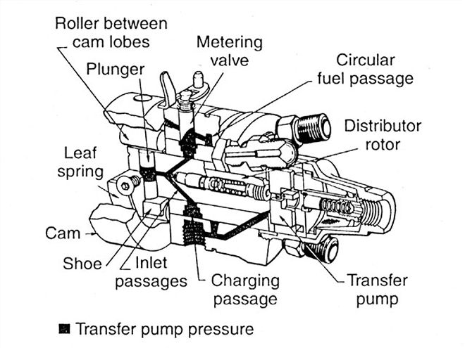
| Fuel flow schematic for a typical DB2 injection pump.
The Origin Of The Stanadyne DB2 PumpWith the DB2, engine rpm is controlled by a rotary fuel-metering valve. When the accelerator is depressed, the throttle linkage opens the metering valve in the injection pump, allowing more fuel to be delivered to the pumping chamber. Thus, the job of the injection pump is to not only accurately time the fuel delivery to the combustion chamber, but to also control the engine speed by varying the air/fuel ratio supplied to the cylinders.
The first practical design for a rotary distributor pump was engineered by Vernon Roosa, a diesel mechanic employed by the City of New York, where he maintained and repaired diesel-driven generators. Roosa patented his design in 1941, but it took him some time to generate any interest in his invention. Following the end of World War II, the Hartford Machine and Screw Company, a machine shop best known for producing aircraft engine components for Pratt and Whitney, decided to test out the Roosa design and brought its inventor to Hartford, Connecticut, to assist in research and development.
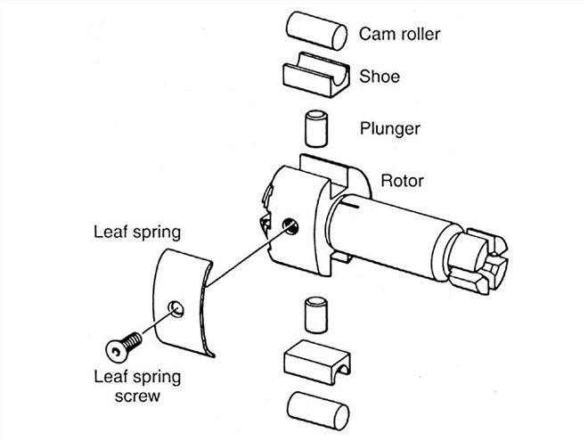
| The pump element and rotor are key components of the design.
Although the Roosa design for a rotary injection pump was not the first, it was easily the most successful and generated many copycat designs. One of these, the American Bosch (Ambac) VE, lasted into the 1990s and was employed on light-duty diesel engines, including the 5.9L Cummins. The main difference between the DB2 and the Bosch VE pump is that the VE pump is a hydromechancial sleeve-metering distributor pump that employs a single-plunger pumping element.
The attraction of the Roosa design was affordability, simplicity, and easy serviceability. The Hartford Machine and Screw Company eventually became part of the Stanadyne Corporation. Thus, the Roosa injection pump became known by the name of its new owners.
| Transfer fuel pressure during the charging cycle.
How It WorksThe DB2 is an opposed-plunger, inlet-metering, distributor-type diesel injection pump. It was designed for low-cost production and simplicity. A typical DB2 (there were slight variations on the design for different engines) has approximately 100 components and only four main rotating members. There are no spring-loaded components, none are lap-fitted in manufacture, and there are no ball bearings or gears. The pump has a single pumping chamber in which two opposed plungers are actuated by an internal cam ring.
The shape of the hydraulic head determines the distribution of fuel between cylinders, and because fuel flow can be preset, lengthy periods on the fuel pump test bench are eliminated.
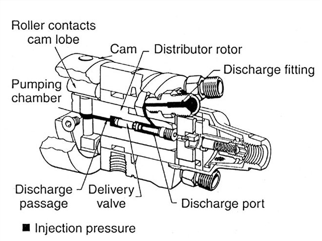
| Operation of the pump during the discharge cycle.
Fuel is drawn from the fuel tank by a mechanical lift pump that is completely independent of the DB2 injection pump, and passes through filters and into the injection pump inlet. From there, fuel flows past the inlet filter screen to the vane-operated transfer pump located in the DB2 pump end cap. The vane-type transfer pump consists of a stationary liner and spring-loaded blades carried in slots at the rear of the transfer pump rotor. As the blades rotate in the liner, they move outward and the volume increases until the leading blade passes out of registry through the inlet slot. The fuel between the blade is carried to the bottom of the transfer pump liner and enters the outlet groove. As a result, pressurized fuel is delivered through the pump into a channel to the hydraulic head passage.
Fuel delivered to the head passage by transfer pump pressure splits in several directions. A portion of the fuel goes to the pressure side of the pressure regulator, while the remainder enters a circular passage in the head from which radial passages lead to the vent wire assembly and then to the governor housing and housing pressure regulator.
The pressure regulator assembly in the transfer pump regulates fuel volume based on changes in pump speed-pressure increases with pump speed.
The vent wire assembly is located behind the metering valve bore, and is made of a J-shaped wire retained in a hollow screw. The wire is free to vibrate and restrict excessive return oil and undue pressure loss.
Fuel entering from the vent fills the housing, lubricates the internal components, and cools and carries away any small air bubbles through the return oil line.
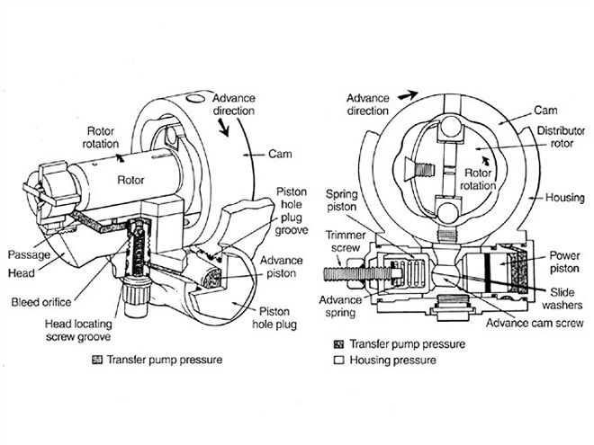
| The advance circuit allows the DB2 to be an excellent performer.
The housing pressure regulator uses a ball-check fitting in the governor cover that maintains even housing pressure, except when the housing pressure cold advance solenoid is operating and allows fuel to return to the fuel tank.
The advance system is a simple, direct-acting hydraulic mechanism. Powered by fuel pressure from the transfer pump, the advance mechanism moves the power piston to rotate the cam to vary the delivery timing. It advances or retards the start of fuel delivery in response to engine speed changes. The advance piston, located in a bore in the housing, engages the cam advance screw and moves the cam in the direction opposite of rotor rotation. When engine speed decreases, hydraulic pressure is reduced and the cam becomes retarded because of low transfer pressure. When engine speed increases, transfer pump pressure increases and moves the advance piston and cam.
In addition to the normal speed advance, a mechanical light-load advance is furnished as a function of throttle angle. It consists of a face cam attached to the throttle lever and an external pivot lever. The mechanical function provides proper advance for light loads when transfer pressure is low and the cam ring is retarded by changing the reference point of the servo valve.
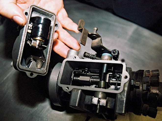
| The DB2 housing cover is easily removed for service and modifications, even when the pump is still on the engine.
GM models that were '81-and-later also were equipped with a housing pressure cold advance solenoid. It consisted of a solenoid assembly in the governor cover and a ball-check fitting. The unit allows more advance at cranking and engine warm-up by reducing housing pressure, which allows the power piston to move further (approximately three degrees) in the advance direction. This results in a slower, more complete burn of the fuel.
The min-max governor regulates the injection pump at low idle and maximum-rated speeds. At speeds between these two ranges, the throttle lever and governor spring directly control the metering valve.
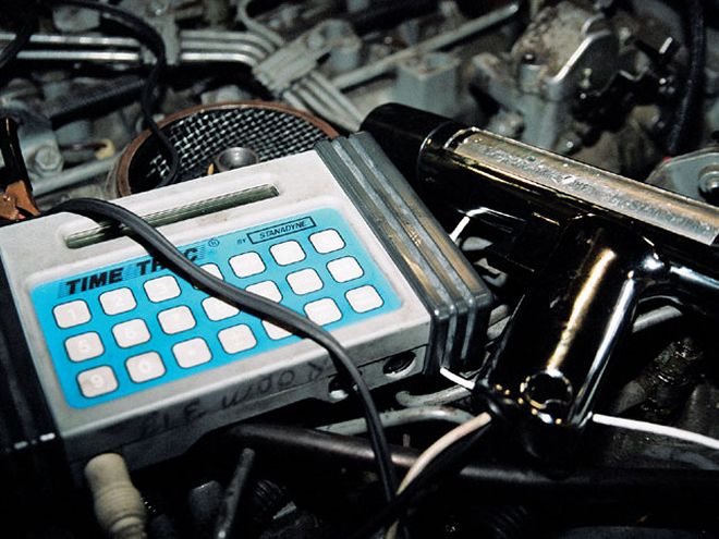
| The DB2 can be timed in a similar fashion to a gas engine using a special Stanadyne Time Trac strobe light.
The governor assembly consists of a cage with flyweights mounted on the rotor and a system of linkages. The movement of the weights acting against the governor thrust sleeve rotates the metering valve by means of the governor arm and linkage hook. The amount of rotation varies the position of the metering valve, thereby controlling the amount of fuel to the pumping plunger. The governor derives its energy from the weights pivoting in the weight retainer. Centrifugal force throws the weights outward, moving the thrust sleeve against the governor arm and rotating the metering valve through a simple, positive linkage.
Retention of heat is a critical factor in fuel thinning after a high-ambient heat soak. As the hotter, thinner fuel passes through the pump, internal leakage increases and reduces fuel output. To compensate for this loss, a bimetallic temperature compensator strip was added to the governor arm to increase the metering valve opening. This provides a compensated idle speed curve and corrects engine idle speed at elevated ambient temperature.
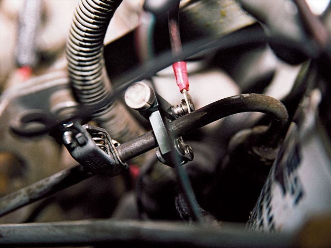
| A sensor that comes with the Time Trac measures vibrations from the number one cylinder fuel line. It senses the injection fuel pulse and illuminates the timing light.
The metering valve allows a varying amount of fuel to pass through the charging passage to fill the pumping plungers in the distributor rotor. As the rotor revolves, the inlet passage registers with the charging ports in the hydraulic head, allowing fuel to flow into the pumping plunger. With further rotation, the inlet passages move out of registration and the discharge port of the rotor registers with another head outlet. While the discharge port is open, the rollers contact the cam lobes and force the plungers together. Fuel trapped between the plungers is then pressurized and delivered through the delivery valve (and the injectors) to the combustion chamber.
The DB2 is near the end of its production cycle, being replaced by electronic-controlled diesels. For many enthusiasts, this pump was on their first diesel, and there are still thousands of them in use in Ford and GM trucks.
Stanadyne DB2 Injection Pump Specs* Rated for up to 25 hp per engine cylinder
* Peak injection pressures to 6,700 psi* 2-, 3-, 4-, 5-, 6-, and 8-cylinder configurations
* All-speed governor
* Built-in automatic advance
* Electric shut-off
* Handles engine speeds to 5,000 RPM