Using a few simple tools and completing in less than an hour, you will learn to repair the common odometer problem found in Ford Expedition models from 1998 to 2001. Specifically, this article will address the 1999 model. Save yourself a few hundered dollars.
Disconnect the vehicle battery under the hood.
The headlight switch knob is its own tool to remove switch.
Remove the headlight switch by turning it to the headlamp ON position.
Next, carefully pry off the knob using a plastic pry tool or flathead screwdriver and soft cloth between pry tool/screwdriver.
Turn the knob 180 degrees around and reinstall so it faces opposite the ON position. Now, turn the knob back to OFF. It should be in a vertical position with back of knob pointing OFF.
Then rotate the knob clockwise as far as possible and hold it in this position. This releases the locking tabs on the back of the switch to enable it to be pulled out of the dash.
Pull and pry switch assembly out. Unplug electrical connector from switch.
Pry out the center trim panel that fits over the steering column, just below the clear instrument cluster. Cover steering column with protective towel. Removing trim panel can scratch the plastic finish of column cover. Using screwdriver and cloth, pry out the clips securing the bottom of the panel then the clips at the top and remove panel.
Remove the curved plastic bezel above instrument cluster by removing the three screws securing it from underneath. Use a short handled philips head screwdriver for this. Tilt the steering column down to its lowest position. Pull the top of the bezel outward and down while also disengaging the lower half.
Now remove the screw behind the headlight switch using 9/32 or 7mm sockets and wrench or driver. Same socket for all panel screws following.
Remove the four screws along the lower edge of instrument panel located behind where the center trim panel was. There are two close together on the left and on the right side between the steering column and dash.
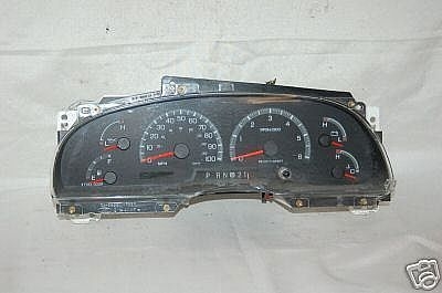
Next, remove the instrument cluster itself. Remove the four screws holding the cluster in place. They are located at the four corners of the cluster and are brass colored.
Pull the instrument cluster straight out and unplug the electrical connectors (2 of them) from behind.
On models with auto transmission, disconnect the gear range
indicator located just under the cluster and held in place by two
pinch clips. Squeeze these to release it.
Using No.15 torqx bit, remove screws from back cover of cluster (cover is white color) opposite the clear lens side. Remove the cover.

Unplug the ribbon cable connection from the green circuit board.
This is located near the bottom right side of board as you are facing
the back of the cluster assembly.
Slowly and evenly separate the green circuit board from the gauge
cluster and gauge pins/posts.
Located the ribbon cable connector socket on the circuit board and
flip over the board to see the pins soldered on the back. You should
see it on the lower left side of the board now. It is just above the
square cut out indention in the board. There are 9 pins in a row
from left to right.
Using your soldering pencil/iron, touch and hold to each pin for 5-7
seconds and then add just a small amount of solder to flow around
the pin. Remove pencil/iron from pin and allow it to cool. Proceed to
each pin till complete.
Installation is the reverse of removal for each of these steps.