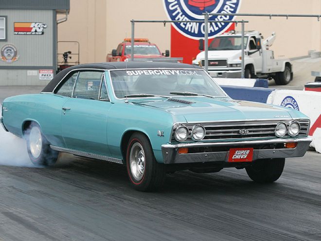
Early A-bodies, like our Project AMD 1967 Chevelle, came from the factory with triangulated four-link rear suspensions. In a time of leaf springs this was a big step up, but the four-link design presented its own set of challenges. First of all, to keep costs down, GM used stamped steel control arms that flexed under load. Now, some flex was needed to avoid binding up the suspension when cornering, but under hard load this flex could cause some pretty sketchy handling characteristics and driveline-killing wheelhop. To fix the wheelhop, heavy-duty arms could be added along with hard bushings, but that caused the suspension to bind in torsion and pretty much ruined how the car handled through turns. Heim ends fixed wheelhop and let the arms articulate but they transmitted a ton of noise to the body. But, no matter which way you went the biggest problem was the arms didn’t provide a way to adjust pinion angle.
Pinion angle is simply the angle of the differential’s pinion in relation to the car’s driveshaft. On a stock car, running stock stuff, having the ability to adjust this angle isn’t that important since the factory dialed it in. But, if you’ve done drivetrain modifications, or lowered the car a lot, being able to adjust your pinion angle is pretty important. We asked the guys over at Currie and they explained that a typical universal joint is designed to handle between 1 and 3 degrees of pinion angle. If a U-joint is pushed beyond this range it can hyperextend and fail, which will most likely ruin your day. Given this, they strive for 2 degrees of pinion angle on a street car. Sometimes people increase the pinion angle to get more bite at the dragstrip, but Currie doesn’t think this is a good idea on a street car. So, if you want more bite at the strip then it’s better to adjust it for the track at the track and for the street on the street.
But why have any pinion angle at all? One would think that he best angle would be zero so that the power could transmit straight into the differential from the driveshaft. In theory that’s true, but keep in mind when you launch hard, the differential will try to rotate upwards and that will change your pinion angle. So while it might be 2 degrees at rest, it could be zero under load from a hard hit of the throttle. The idea is to compensate for this differential rotation without letting the pinion angle go negative (beyond zero or hyperextending).
On our Project AMD 1967 Chevelle we had installed a modern-overdrive 4L80e transmission. This required us to lower the transmission crossmember just a touch, but it was enough to change our pinion angle. Since we had the stock arms we were pretty much stuck with what it was. The Chevelle also had some wheelhop at the strip so we decided to fix both issues with a set of rear control arms from Currie Enterprises.
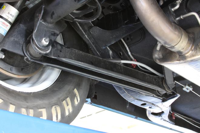
01. Our 1967 AMD Chevelle was equipped with just the basic stamped steel control arms. Sometimes, typically on SS models, these arms will be beefed up with steep plates, and while they are much better, they can still flex and are not adjustable.
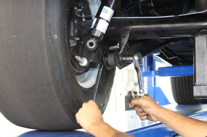
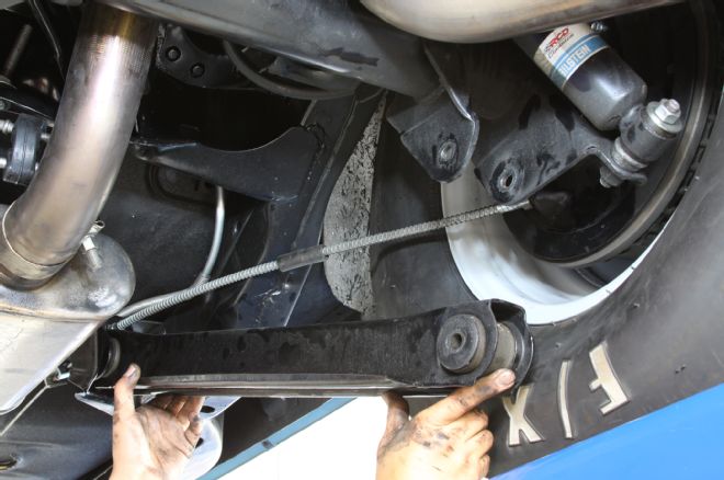
02. The idea was to do one side at a time to keep the rearend positioned correctly. We disconnected the shock, raised the body, removed the rear spring, and supported the differential with a trans jack (or a couple of pole jacks). With that done, we unbolted the lower control arm.
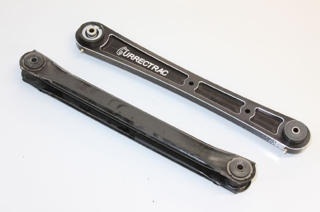
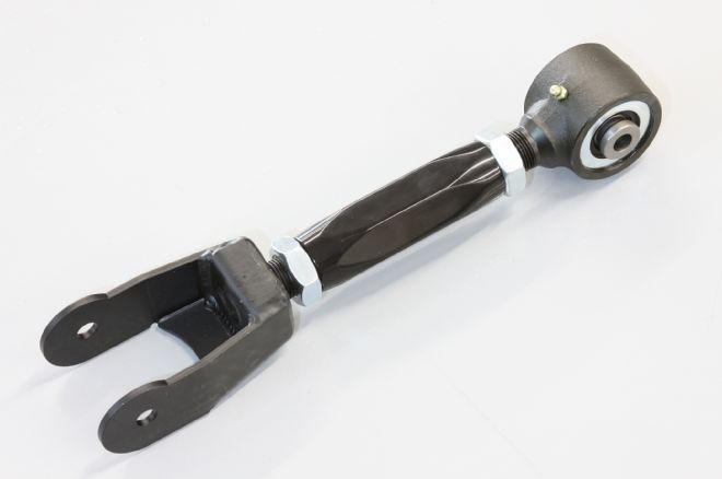
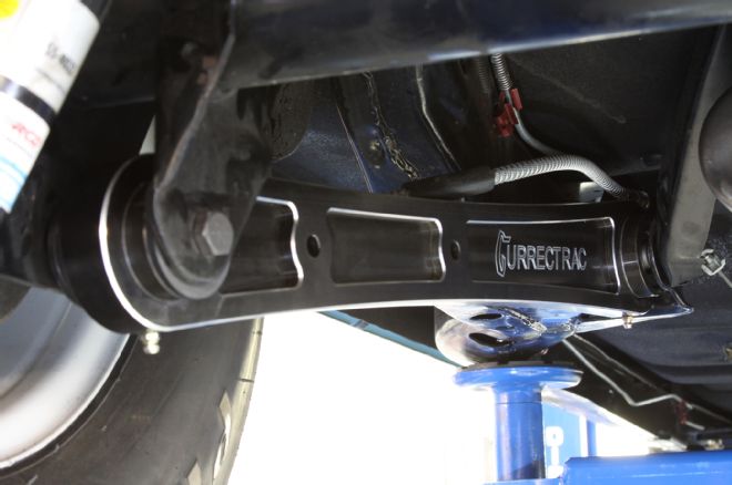
03. Here you can see the billet 6061-T6 aluminum Currie Currectrac arm (PN CE-7011LA) next to the stocker. It should be obvious which is stronger, but the Currectrac arm has other advantages as well.
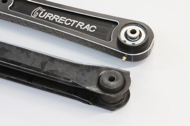
04. The biggest upgrade is the urethane bushed Johnny Joint rod end that provides a range of motion (30 degrees of travel, which is more than a Heim-style end) without any non-linear binding. It’s greasable, rebuildable, and light years better than the stock rubber end.
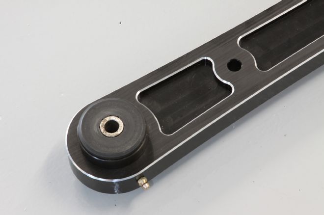
05. On the other end is a greasable urethane bushing. This dramatically reduces the amount of noise transmitted into the body of the car. The arms also have mounting provisions for stock or aftermarket sway bars. Plus they look killer, which is always a bonus.
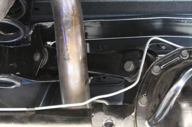
06. The triangulated upper arm was a bit harder to get to, but it was simply held in place with two fasteners.
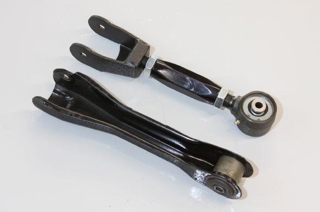
07. Currie’s replacement upper control arm (PN CE-7011C) is a “turnbuckle” style design. This means the center section can be rotated to adjust the arm length (and therefore set pinion angle) without removing either end from the car. On the differential end, the steel fork-bracket mounts to the busing on the differential just like the stocker. On the other end there’s a re-buildable Johnny Joint end, just like on the lower arm.
08. To get in the ballpark, we adjusted the Currie arm to the same length as the stock one from the car. Once everything is together we can adjust the Chevelle’s pinion angle.
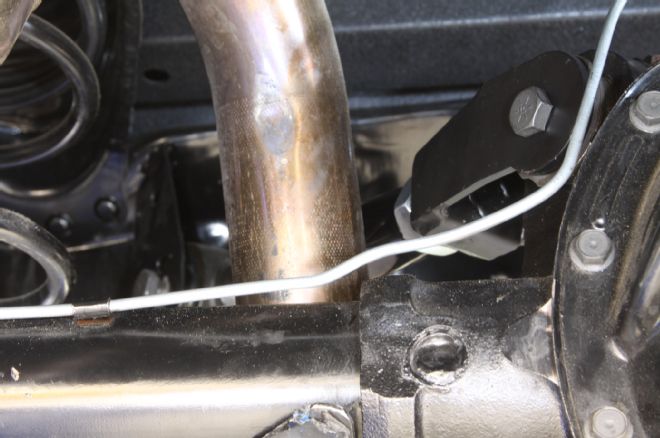
09. With all the bits in the way, such as the exhaust, the upper arm is hard to photograph, but it bolted in just like the stocker. On some 12-bolts it may be necessary to grind off a bit of the steel fork-bracket on the differential end if there’s interference to the gear case.
10. We then repeated the procedures on the passenger side of the Chevelle.
11. A large Phillips screwdriver, or tapered guide pin, is helpful in getting the rear control arm lined up with the bracket on the axletube.
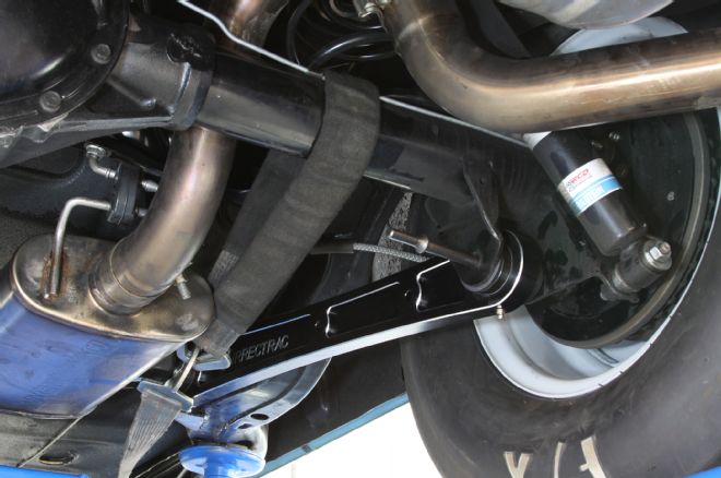
12. With all the arms installed we went back and torqued down all the bolts and hit the bushings and Johnny Joints with some grease.
Setting Pinion Angle
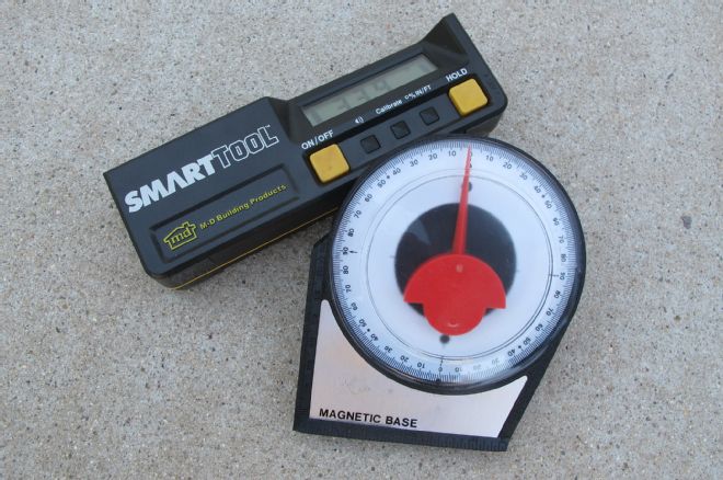
Currie takes the process one step further by factoring in the transmission output shaft’s angle in determining where the pinion angle should be set. Sometimes corrections need to be made at the front of the vehicle to ensure that the engine and transmission are sitting in the proper location. According to Currie, the average car builder should try for 1 to 3 degrees between the tailshaft of the transmission and driveshaft, and 1 to 3 degrees between the driveshaft and pinion. Furthermore, the two angles should be nearly equal (between 1 and 3 degrees), but always opposite. The turnbuckle design of the upper arms will make it easy for us to add a bit more pinion angle at the strip. A digital level or magnetic protractor makes getting the angle a snap.