A few weeks ago we swung by the Total Cost Involved RnD workshop and showed you the start-to-finish installation of Total Cost Involved Engineering's awesome bolt-on IFS for early ('63-'72) C10s. As that day's install progressed and we talked back and forth, the guys mentioned that they'd also developed a new bolt-on torque arm/coilover rear suspension system to go along with their bolt-on IFS. Well, after seeing how easily the front suspension upgrade went together I was looking forward to observing the rear suspension install as well, so we made plans to get together again a few days down the road.
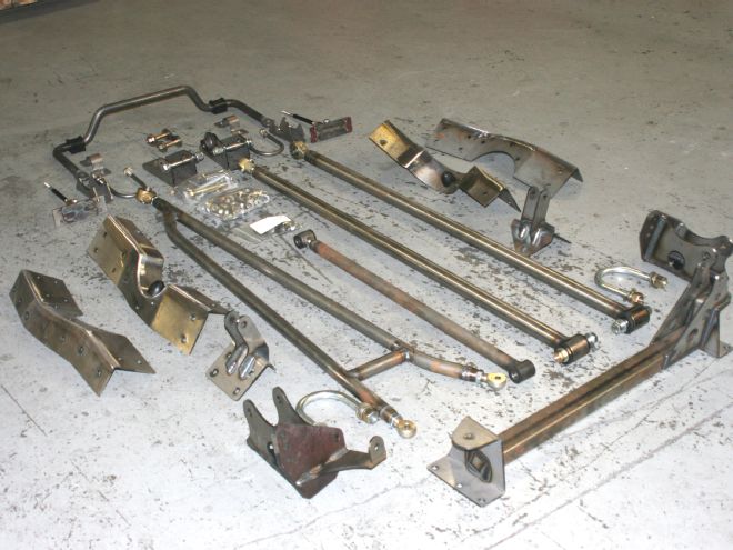
I showed up back at the shop bright and early a few days later camera in hand and ready for another photo session. The guys were ready as well, and had all the component parts of the torque arm system laid out on the floor next to the C10 chassis. Just by eyeballing the components I knew that this fully bolt-in install would be just as straightforward as the IFS install had been so I readied my camera, stepped back out of the way ready to let the guys get to work.
Before they started in earnest though they pointed out a few important points regarding the install. First, the job does require the pickup bed be removed from the chassis, and also originally there are three rear crossmembers at the rear portion of the frame that are relevant to the installation. The large forward most crossmember remains, but there are two rivets per side that'll need to be removed, as will the factory upper shock mounts, and a small flange sticking out from the bottom of the framerails that will need to be trimmed (in order for the support plates to fit flush against the outside of the framerails).
Moving rearward, the next smaller crossmember will have to be removed altogether. The instructions that come with the setup will give you all the specifics, but don't fret; it's not a big deal. And finally, the truck must be securely positioned on jackstands as close as possible to ride height. Also, keep in mind that the guys have done this install numerous times and the steps shown here may not exactly mirror the steps shown in the instructions supplied with the kits. With these few caveats brought to my/your attention the real work began.
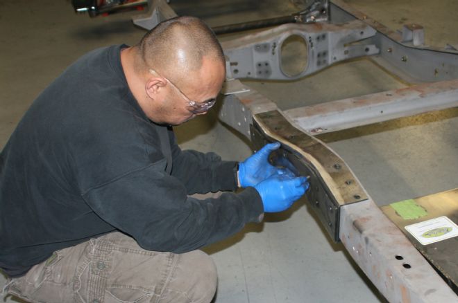
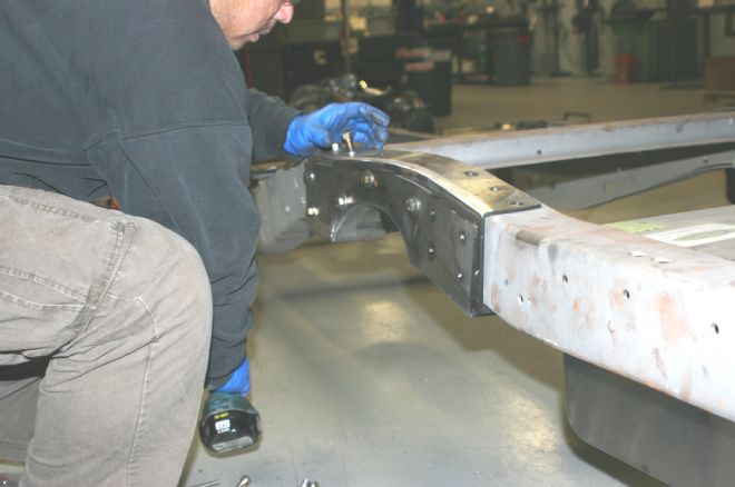
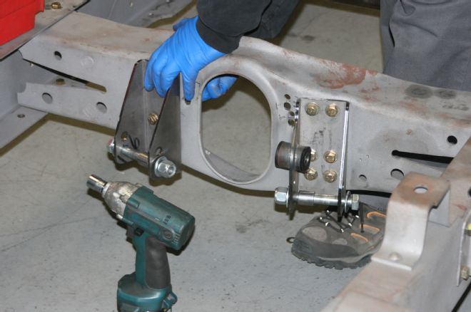
Starting on one side, a C-notch support plate is placed onto the frame at the axle center line and lined up with the four holes in the frame that match with the plate (in most cases two on the side and two on the top). The frame holes may be smaller than the four matching holes in the C-notch support plate as well. If so they'll have to be drilled out to 7/16-inch. They drilled one of the top mounting holes and inserted a bolt and snugged it up, then using a marker traced the notch opening onto the side of the framerail. This was repeated on the other framerail and then both support plates removed and the frame notches on either side cut out (this can be done using a saw, cut-off disc, or plasma cutter if you have one).
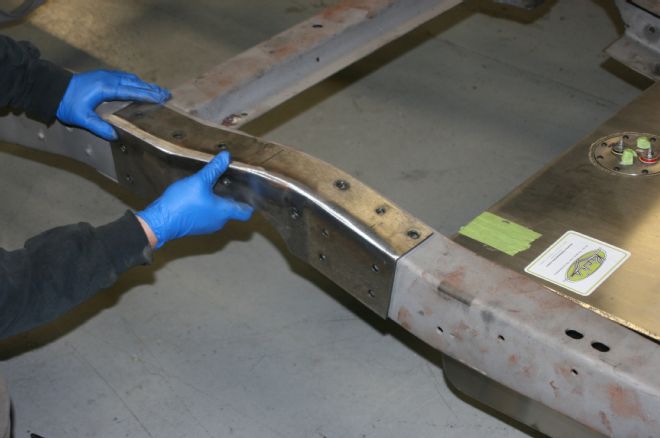
With the C-notches cut out of each framerail both C-notch support plates and the top bolts are re-inserted. Next, the second set of C-notch plates are slid into the notch so they are sandwiching the support plate between it and the framerail, then they made sure the mounting holes lined up with the ones in the support plates and framerails. They clamped the notch and support plates to the framerail as well and used the plates as a guide to drill the balance of the top, side, and bottom mounting holes.
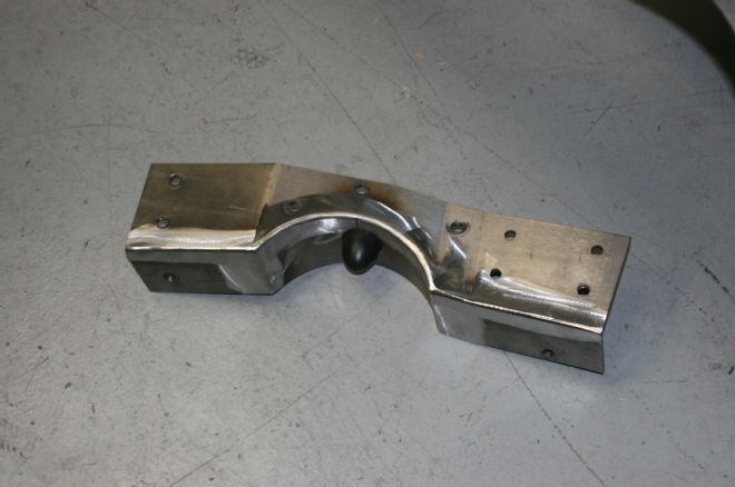
With both plates in place on the framerail and all of the C-notch plates' mounting holes drilled, the forward most top mounting bolt was inserted and tightened and the top rear most bolt installed and slightly snugged.
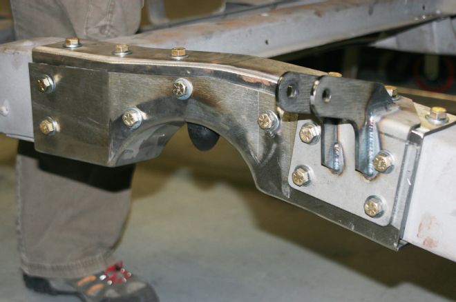
Next, the upper shock mounting brackets were installed. They're side specific with the shock flanges tilting toward the front of the chassis while in hand and vertical when in place on the frame. The mounting bolts were inserted starting with the top bolt. The balance of all the mounting bolts are then inserted and torqued to 70 lb-ft. (Including the bottom mounting bolts as well.)
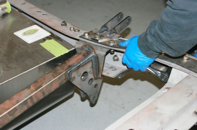
The Panhard bar crossmember came next. The top bolt and nut from each side shock mounting plates were removed and the crossmember put in place with the Panhard bracket on the left (driver) side of the chassis.
The mounting holes on both sides are lined up and the Panhard bar crossmember attached to the frame.
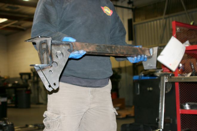
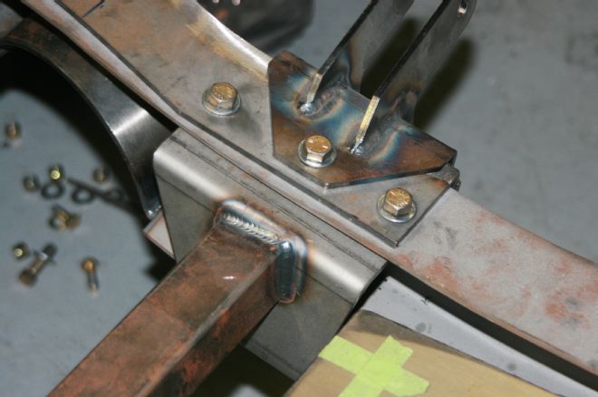
Moving forward on the chassis, the original track bar mounting brackets are removed from the crossmember by drilling out the original rivets. (Note, for the trucks that have 'em, the two-piece driveshaft mount will have to be removed from the crossmember as well.) The original brackets are then replaced with the brackets contained in the kit. The right (passenger) side bracket is the one with the additional torque arm mount.
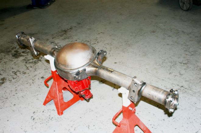
Next came the rearend installation. In this case a Currie 9-inch was being used, but Total Cost Involved offers mounting accommodations for other rearend choices as well. This rearend had been outfitted with the needed bracketry ahead of time and the company will provide instructions that pertain to your rearend of choice.
The lower shock mount brackets are attached to the rearend. There are left and right brackets, the right (passenger) side is pictured here; it has an additional bracket off the back for attaching the Panhard bar.
The left side bracket is shown here. Both sides are attached to the rearend housing using the U-bolt assemblies supplied in the kit.
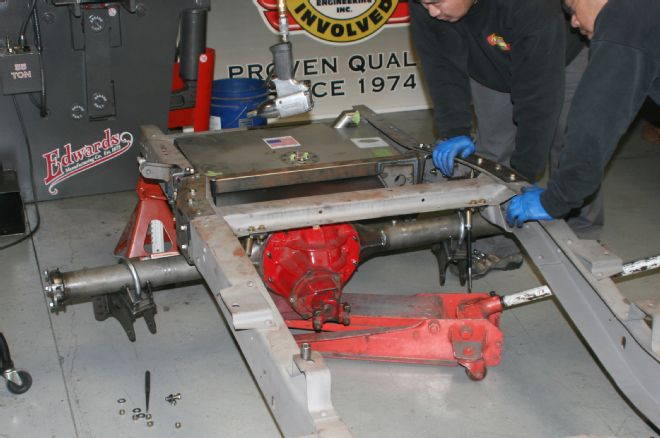
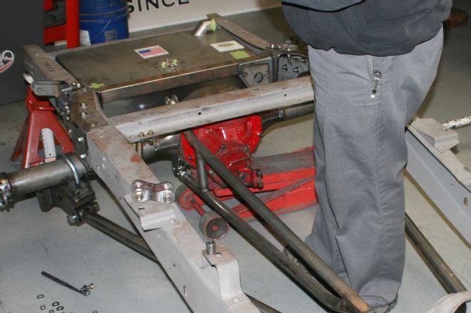
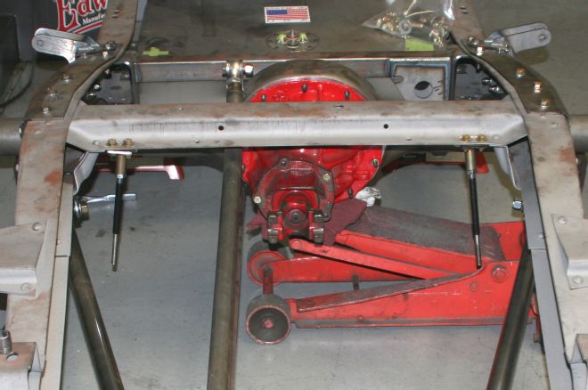
The rearend assembly was then slid into place under the frame and lined up for installation of the new Torque Arms.
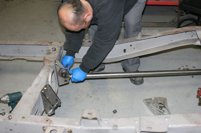
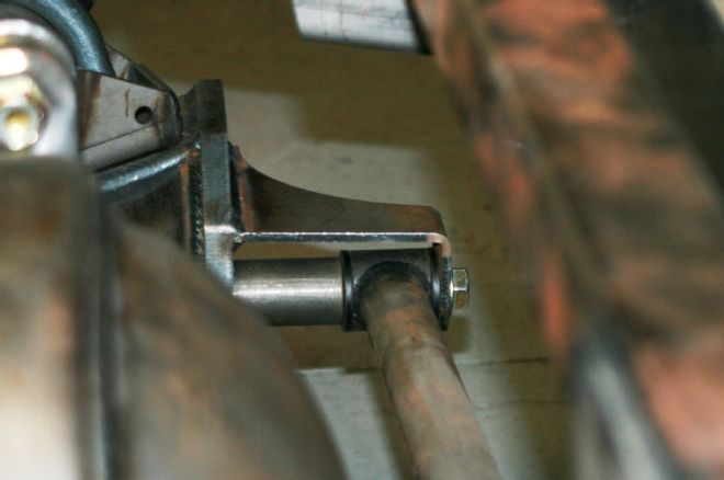
The bushing ends of the link bars are inserted into the rear brackets and the bolts and nuts inserted and torqued to 100 lb-ft.
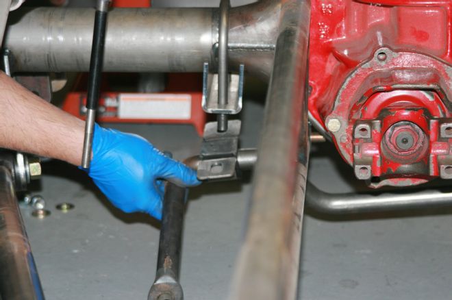
Position the adjuster side of the link bars into the brackets on the driveshaft loop crossmember with the adjusters against the outside edge of the brackets and spacers between the adjusters and the inner ears of the brackets. You may have to make small length adjustments to the bars to keep the rear axle in the proper location.
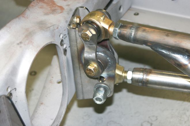
The Panhard bar came next. One end was slid into place in the rearend housing bracket and the opposite side into the frame bracket and bolts and nuts inserted and tightened.
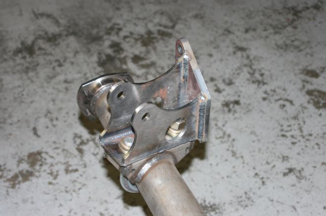
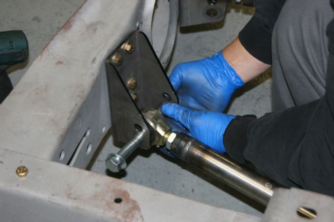
At this point it was time to install the torque arm. The rear section of the arm attaches to the brackets on the rearend housing and the front will attach to the right side link bar bracket. It will be at this point that the pinion angle is to be addressed (the included instructions will give specifics in this regard).
The front of the torque arm is attached via dog bone brackets bolted to the single bushing on the passenger side link bar bracket on the driveshaft loop crossmember. One dog bone goes on either side of the bushing and the torque arm is attached to the upper portion of the dog bones.
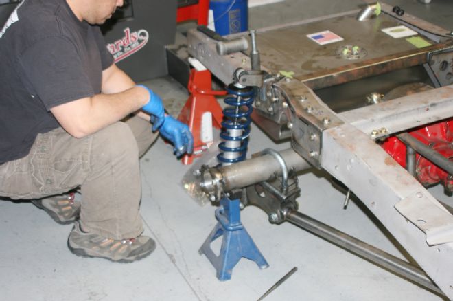
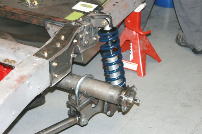
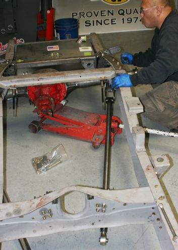
With the torque arm and link bars installed the coilover shocks came next. The lower mounting points attach to the rearend housing brackets and the uppers to the brackets attached to the framerails.
The final portion of the install was the addition of a rear sway, or stabilizer bar. A pair of stabilizer links are bolted to either side of the crossmember (replacing the original rivets) using the hardware supplied in the sway bar kit.
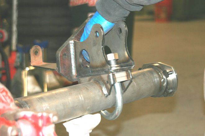
The stabilizer bar brackets bolt to the axle tubes and the bar itself attach to the brackets via bushings and U-clamps.
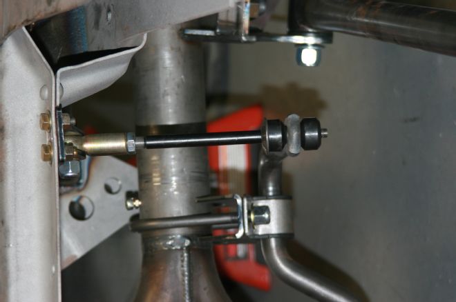
The stabilizer bar is attached up front by sandwiching the flattened ends between a pair of bushings and washers with the stabilizer links passing through the bushings, washers, and bar ends as shown.
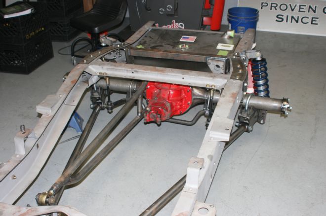
And there you have it, a great handling, easy to install bolt-on torque arm rear suspension setup that is the equal of the Total Cost Involved bolt-on front IFS system — both of which will be as at home on an autocross track as they would on the street.