There's only so far you can lower a vehicle before the suspension bottoms out, or the rearend hits the chassis. We knew when we planned out this '56 F-100 frame that we'd have to C-notch the framerails for clearance if we were to achieve the desired ride height. Art Morrison Enterprises installed their front and rear suspension at the beginning of the project, while we'd tackle the C-notch ourselves at a later date. That time had come!
When we received the rolling chassis back from AME, there was a little under 2 inches clearance between the rearend and frame, which clearly wasn't enough. We decided to C-notch the rails by another 4 inches, giving us plenty of suspension movement and room for a bumpstop. However, this would put the top of the C-notch very close to the top of the rails, and given that the coilovers mounted behind the rearend, and thus the rails had to retain plenty of strength, substantial additions to the framerails were required to prevent the rails bending.
We also elected to raise the entire bed floor rather than just a section over the rearend, retaining a factory appearance. This entailed fabricating new mounting lips around the entire perimeter of the bed, as well as a framework underneath the floor, replacing the two factory crossmembers. When finished, to the uninitiated, the floor will appear factory. An added bonus means we'll have extra room to mount the gas tank under the floor without it hanging down too low.
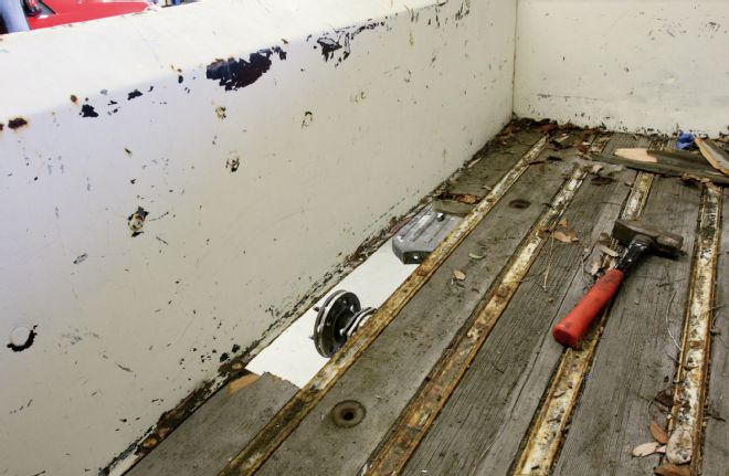
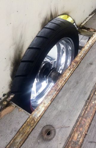
1. The bed still fit on our chassis after the modifications by Art Morrison Enterprises, but the new 20x12 Billet Specialties wheels weren’t going to fit and clear the stock bedsides. The first order of business was to remove a section of the original wood floor.
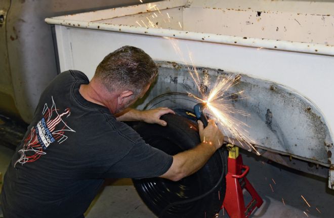
2. Using a space saver wheel and tire as a guide, we used our Miller plasma cutter to remove enough sheetmetal to clear the new rubber.
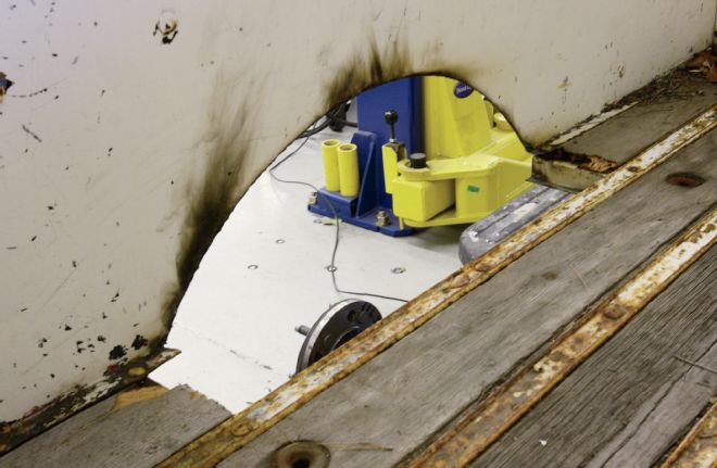
3. Using the space saver ensured a nice even semi-circular cut.
4. As we didn’t have the new wheels and tires yet, we borrowed a set of 20x8 wheels. Though not the right width, they were the correct overall diameter.
5. We quickly hung one of the old rear fenders to get an idea of the ride height. Our calculations had worked out perfectly, with the top of the wheel lining up with the fender lip. The new wheels will be 1-inch further inboard to clear the lip.
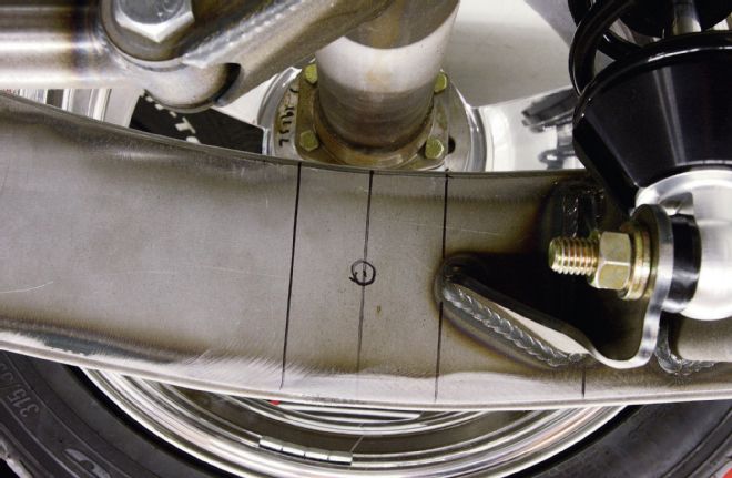
6. We marked the chassis rail with the centerline of the rearend, plus the width of the axle tubes.
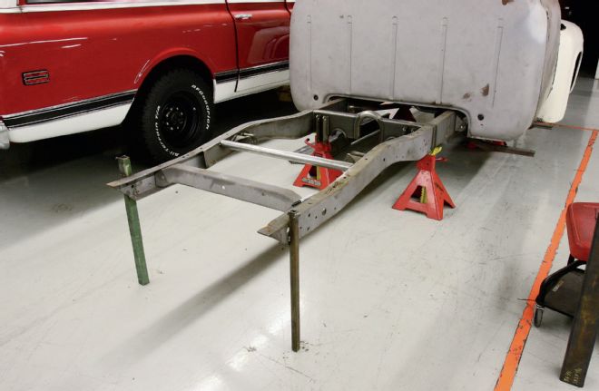
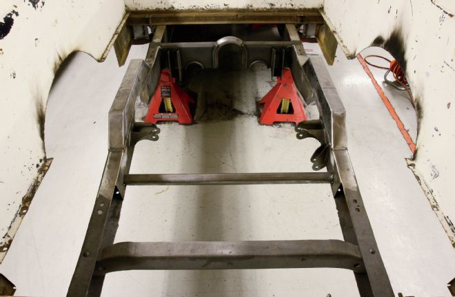
7. The bed was then removed, as well as the rearend and suspension, to prevent the latter becoming covered in debris from the next stage of work. The chassis was set up to be horizontal front to rear and side to side. We also temporarily welded “legs” from the ends of the rails to the floor, which would allow us to see if the rails warped during forthcoming welding.
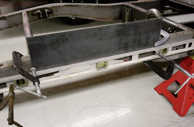
8. With a level clamped to the sides of the rails, we could clamp a length of 3⁄16-inch plate in place. The same thickness as the rails, these will form the chassis kick-up.
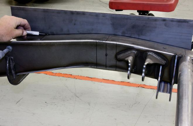
9. The plates were then marked for plasma cutting the top of them 3 inches above the top of the original kick-up.
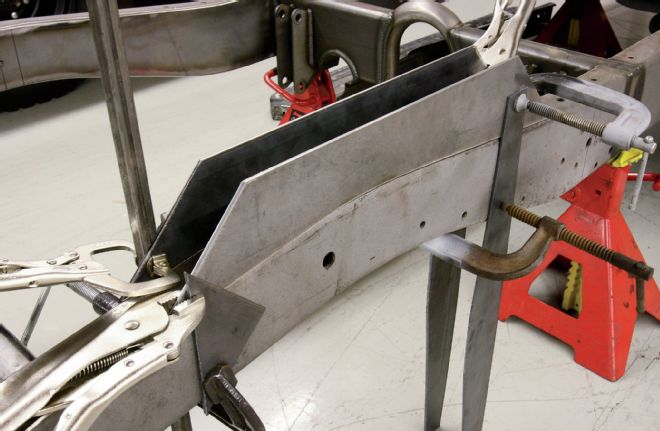
10. With two plates plasma cut to shape, they were clamped in place as shown, so their outer faces aligned with the sides of the chassis rails.
11. We cut three lengths of 1⁄2-inch tube we had laying around, to act as spacers, welded them in place, then started tack welding the kick-up plates to the rails.
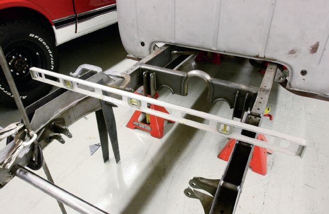
12. We broke out the level once again to ensure the kick-ups were even side to side and diagonally.
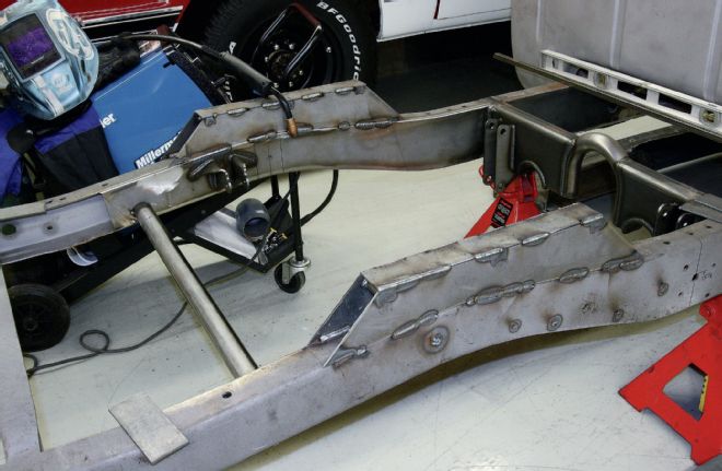
13. With both kick-ups in place we continued welding, an inch or so at a time to minimize warpage, and added the top plates as we went.
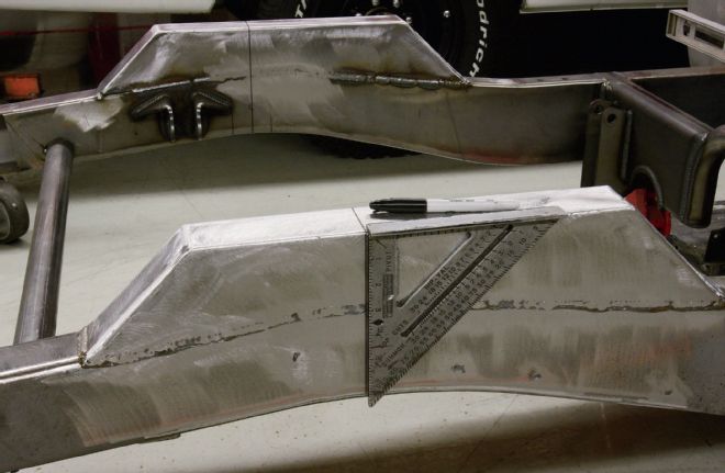
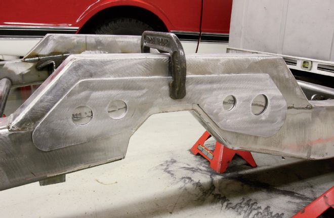
14. With closing plates on the ends, and the welds dressed, we transferred the axle centerline to the outside of the rails…
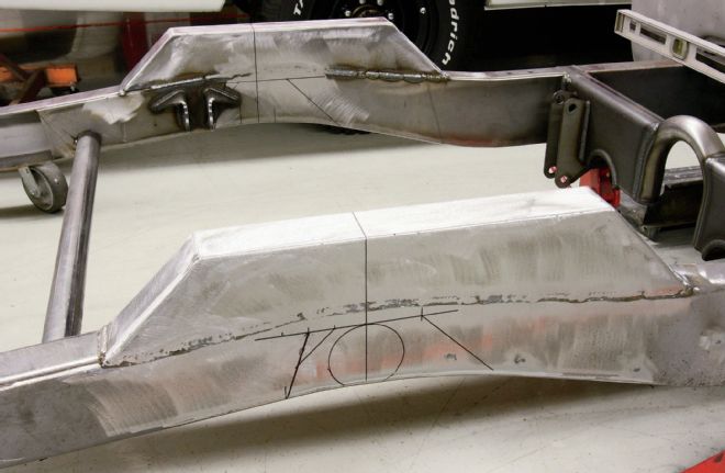
15. …then marked the location of the axle tubes at the top of the desired C-notch, and marked the shape of the C-notch around that. Not wishing to cut into the AME coilover mount gusset too far, we decided to cut the rear of the C-notch to allow as much of the gusset to remain as possible.
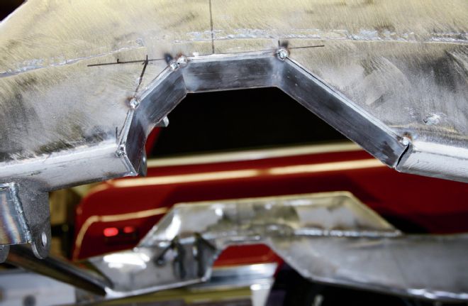
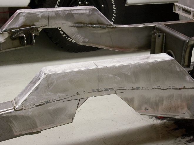
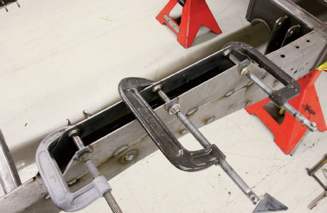
16. With the section removed using a cut-off wheel, we bent two lengths of 2x3⁄16-inch plate to box in the C-notch.
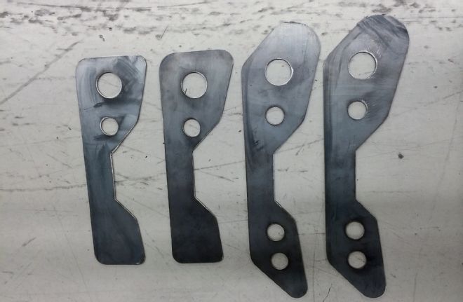
17. The plasma cutter and a couple holesaws in a pillar drill made short work of these plates, which will be welded around the C-notch for added strength. We opted to do this as the coilovers mount behind the axle.
18. Here’s how the strengthening plates will mount. We’ll also weld around the circular cutouts, maximizing the added strength across the welded joint. This is why we ground the welds on the outside of the ’rails.
19. With the C-notches done, and the remainder of the bed floor removed, the bed was placed back on the chassis.
20. Astute readers will realize that the original floor would not clear the C-notch, and we’ll either need a raised section across the center of the bed, or what we consider preferable, a flat floor, raised to clear everything. We started fabrication by clamping lengths of thick-wall 1-inch box section on the outsides of the bed to ensure it remained straight.
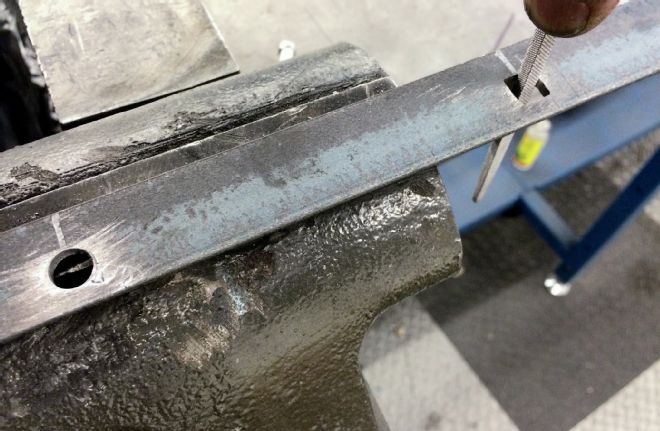
21. We wanted to retain a stock appearance to the raised floor, which means replicating the lips that the original bolts to along the lower edge of the bedsides. We used 1x1x1⁄8-inch angle, and copied the mounting holes over. Of course we had to file each one square individually, in order to use the stock-style carriage bolts.
22. We also needed to fabricate an under-floor framework, as the two stock bed-wood crossmembers were now redundant. We used more 1x1-inch box section, and welded them to 1⁄8-inch plates welded to the lower bedsides, with gussets. The new floor will be 4 inches higher than the original, and the wood will sit on the new crossmembers, and bolt to the angle.
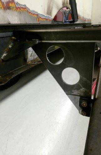
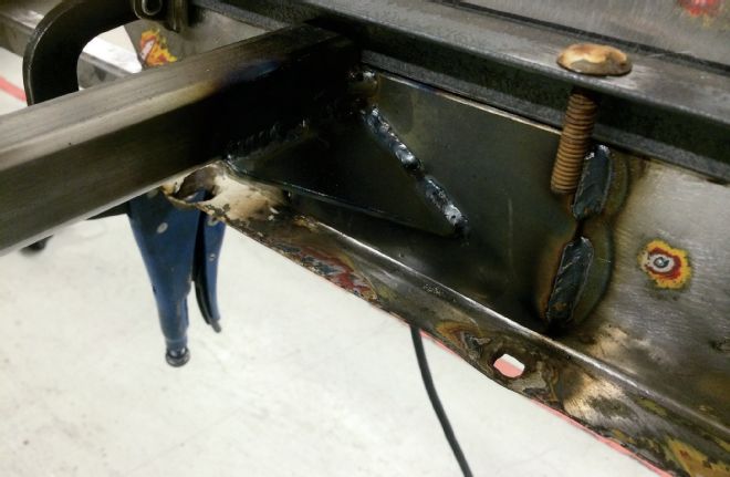
23. We then fabricated four triangular mounts that weld to the crossmembers and bolt to the chassis rails. Front to rear gussets were deemed unnecessary as the forward-and rearward-most mounts will prevent the bed moving in either direction.
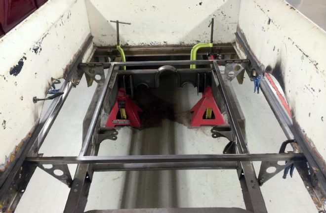
24. The completed framework. We won’t cut the lengths of angle or the braces on the outer bedsides until the new wheelhousings are in place.