Here's a bit of little known gearhead knowledge for hot rodders; when the Mustang was being prepped for its world-changing launch back in 1964, the original plan was for it to come with an independent rear suspension (IRS) as standard equipment on Shelby GT350s and as an option on standard Mustangs. Designed by famous Ford engineer Klaus Arning, the suspension geometry was derived from the Ford GT racing program and would actually have had a slight rear steer effect during suspension travel that would toe the outside wheel slightly inward, and toe the inside wheel slightly out making the steering feel more responsive. That would have helped the rearend rotate into turns, which would have made the handling very nimble and place the Mustang somewhere between ponycar and true sports car. What happened to it? The bean counters killed it, of course.
With that program axed, the only muscle/sports car to be bestowed with an IRS during the 1960s was the Corvette. That's too bad, because the technology was obviously there for both Ford and GM, but neither stepped up to offer the option to the public in their ponycars. Perhaps that's because drag racing was by far the most prevalent sport for American hot rodders, or perhaps it was because the general public just wasn't aware of the benefits enough to demand it.
So what's so great about IRS versus a straight axle? Well, on a purpose-built road course with a perfectly smooth and prepped surface designed for high-speed racing the benefits between a straight axle and an IRS won't be obvious, but that's not where you're going to spend most of your time with your car. Out in the real world the roads are uneven, cracked, and bumpy, and that's where IRS really shines.
Ever gone through an unexpectedly rough section of pavement on a turn in wet weather and had the rearend skip and try to step out on you? While a solid axle has to seesaw a 100-plus pound piece of iron up and down to compensate for road irregularities—reducing the tire's contact patch while doing so—an IRS drastically reduces the unsprung weight per side and allows each tire to adjust to changes quickly on its own without interfering with the other side of the car. That not only means an inherently smoother ride than is possible with a solid axle, it also means more consistent rearend traction. There's really no better option for real-world daily driving and touring, and it's also terrific for autocrossing and handling events, which are often setup on less than optimum surfaces like parking lots.
Of course there aren't too many ways to get an IRS under a Mustang, and none have offered an absolutely easy, home garage bolt-in solution until now. When you're ready to give your Mustang the type of exceptional ride and handling it could have had, Heidts Hot Rod Shop now has you covered with their easy-to-install Pro-G IRS system. You might think that adding a modern, clean-slate independent rear suspension would be difficult, but it's not. We were pleasantly surprised to discover we could rip out the leaf springs and original 8-inch rearend and have the Pro-G hanging in place in any 1964-70 Mustang or Cougar in about two days. Watch how it all goes together in a 1966 Mustang convertible!
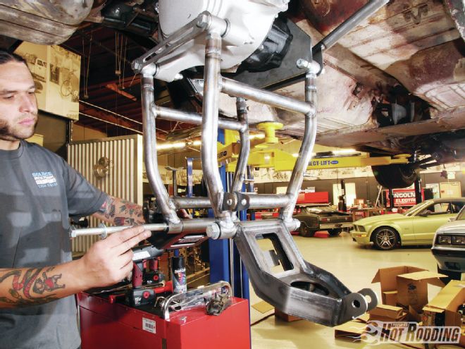
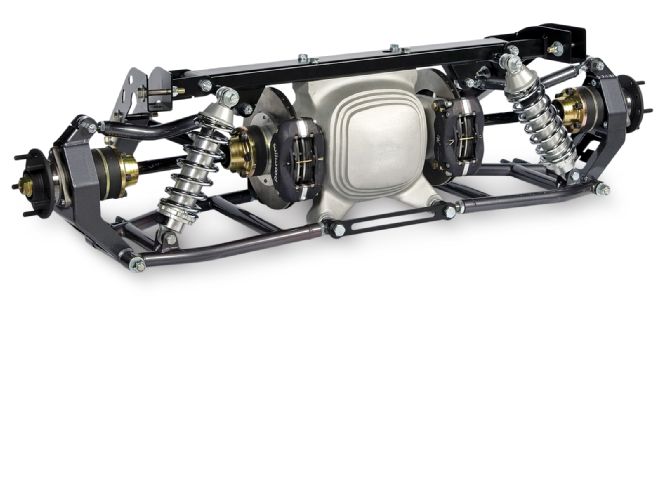 Heidts designed the Pro-G IRS with high-horsepower capacity in mind with heavy-duty CV joints. The upper link produces -.5 degree of camber curve at three quarters of total travel, especially useful during very high cornering loads. A pair of forward struts attaches to the subframe connectors and ensures the wheels stay in place during hard acceleration.
 Before turning a single bolt, make sure to measure the location of the axle on each side of the car. Use a set reference point, such as the lower front of the quarter-panel where it meets the rocker, and measure to the centerline of the hub. This should be very close from side to side.
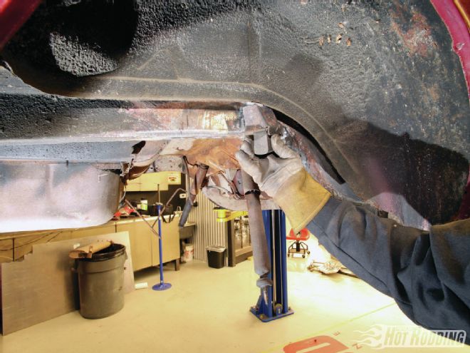 We won’t bore you with the disassembly, but you’ll need to remove the rearend and leaf springs, driveshaft, e-brake cables, and the rear section of the exhaust. The first bit of cutting will be removal of the stock bumpstops. We’re using a lift for ease of photography, but this swap could be done with jackstands.
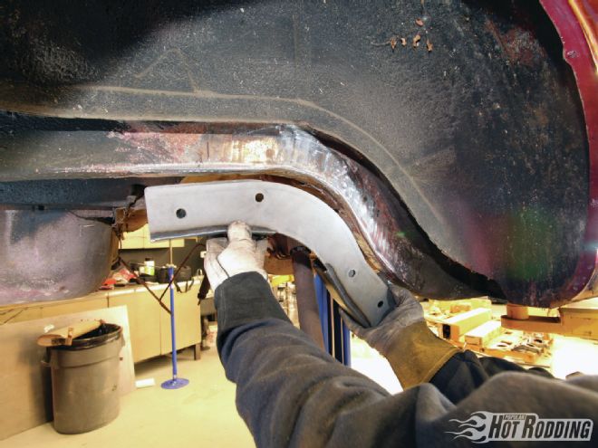 This is one of the most critical steps in the install since proper placement of the frame saddles will ensure the rearend is square in the car. Use the shape of the rear subframe to initially locate the saddles and clamp them in place (some cleaning of the rail may be required).
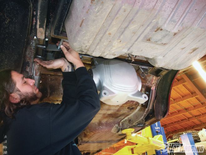
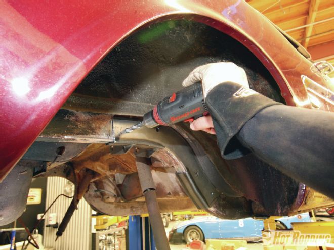 The measurement from the rear edge of the saddles to the front edge of the rear leaf-spring shackle mount should be 24 inches; there will be some slight deviation due to chassis tolerances. The important part is to make sure the measurement is equal on each side before drilling. Once you have that locked in, use the saddles to locate and drill the .5-inch holes for the mounting bolts. It is a bit tricky to drill a single hole through both sides of the frame and keep the bit straight, so we’d recommend drilling the inside and outside frame holes independently where possible.
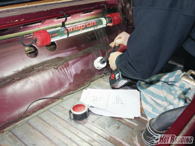 We need to provide access to the upper mount for the crossmember and coilovers; using the provided diagram, drill two 3-inch holes into the trunk floor just above the fuel tank.
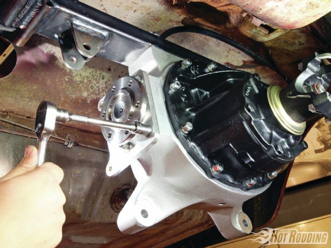
 Now we’re ready to start assembling the suspension. The upper crossmember is bolted to the housing with the upper link mount biased toward the bottom. The .5x2.5-inch bolts are torqued to 70-75 ft-lb. All the assembly hardware is supplied by Heidts in the kit.
 The crossmember and housing install to the mounts on the frame saddles. You’ll need to slide the bolts through holes previously drilled in the trunk floor to get them through the mount.
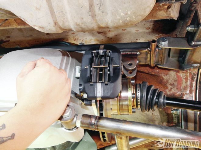
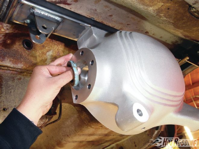 The seals for the stub axles need to be installed with sealant. Slide them in with the lips pointing forward and press until they bottom out on the shoulder in the bore. A seal installation tool is recommended to ensure they are perfectly square, but it’s not required.
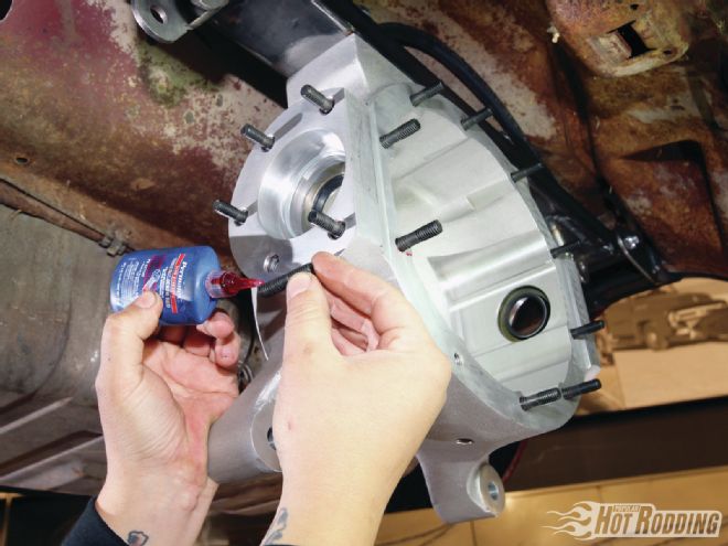 The mounting studs for the third member and the brake caliper mounting plates should get a liberal dose of thread locker; you don’t want these backing out. The 1.5-inch studs for the retaining plates are installed into the ends with roughly .975-inch sticking out, while the 2-inch third member studs should have roughly 1.125 inches sticking out.
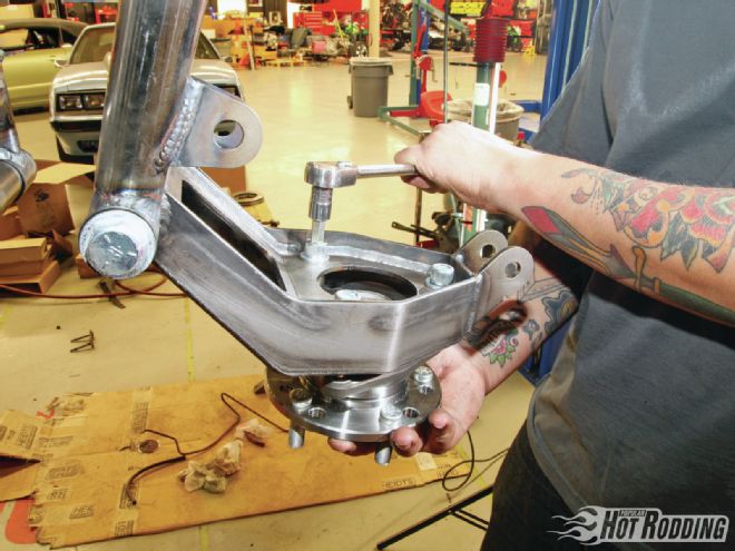
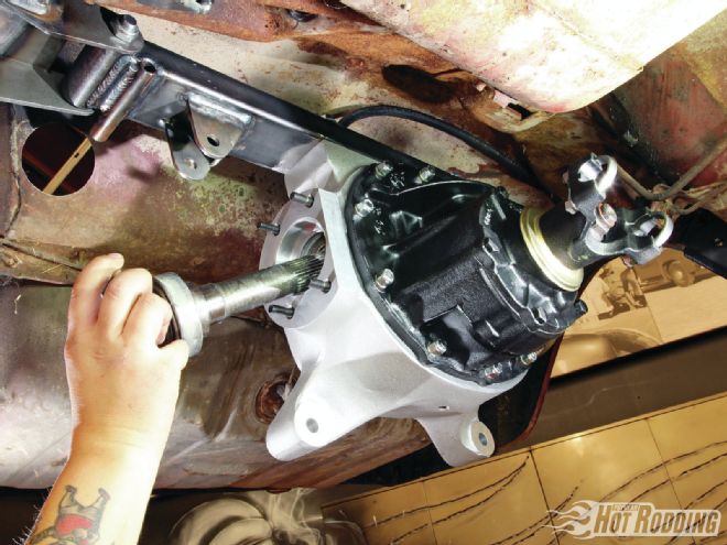 Heidts can supply a tough third member spec’d to your preferences with the kit, or you can supply your own 31-spline unit. After smearing a little gasket sealer on both sides of the third member gasket, it installs with 10 Nylok nuts and AN washers. The axle stubs get a smear of white lithium grease and are slid in until they bottom out; the slightly longer shaft installs on the passenger side.
 The caliper mounting plates install with the threaded inserts toward the axle stubs. A notch on the face of the stub will allow a socket and extension to pass through for tightening the Nylok nuts.
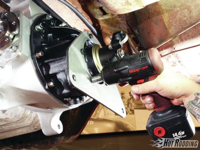
The pinion mount plate installs using the same boltholes the pinion support uses to mate to the third member. The original bolts are swapped out for longer ones included in the Heidts kit.
The caliper mounting plates install with the threaded inserts toward the axle stubs. A notch on the face of the stub will allow a socket and extension to pass through for tightening the Nylok nuts.
The pinion mount plate installs using the same boltholes the pinion support uses to mate to the third member. The original bolts are swapped out for longer ones included in the Heidts kit.
 The pinion plate provides a mounting location for the pinion support crossmember. The outer mounts attach to the forward holes of the frame saddles.
 Now we’re getting to the cool stuff! The lower control arms are installed to the housing and pinion plate with ⅝-inch bolts. Make sure to include the washers between the rear adjusters and the housing. Leave adjusters a little loose for now since we need to set camber here later. The adjusters should be set equal to start so the arms are straight and parallel. The uprights are installed with 10.5-inch bolts and washers, and should be left only snug for now.
The hub assembly is installed into the upright with 12mm bolts torqued to 65 ft-lb. Heidts recommends locking compound on these bolts as well.
Now we’re getting to the cool stuff! The lower control arms are installed to the housing and pinion plate with ⅝-inch bolts. Make sure to include the washers between the rear adjusters and the housing. Leave adjusters a little loose for now since we need to set camber here later. The adjusters should be set equal to start so the arms are straight and parallel. The uprights are installed with 10.5-inch bolts and washers, and should be left only snug for now.
The hub assembly is installed into the upright with 12mm bolts torqued to 65 ft-lb. Heidts recommends locking compound on these bolts as well.
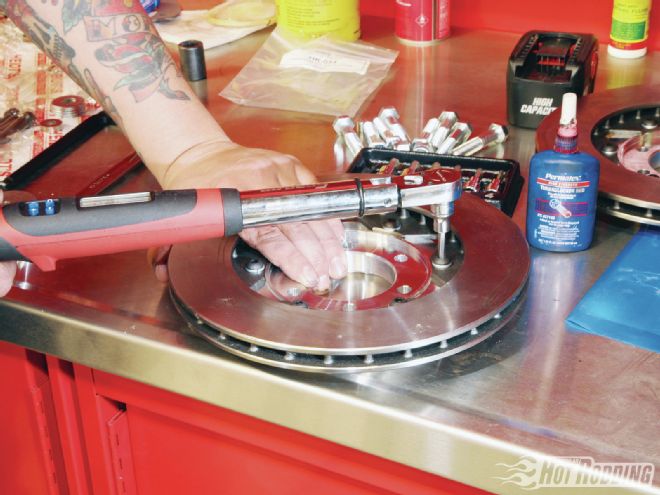 The rotors are attached to the rotor adapters with the shouldered side of the adapter facing the flat side of the rotor. The 5/16-24 button heads and lock washers are torqued to 180 in-lb (15 ft-lb) with thread-locking compound.
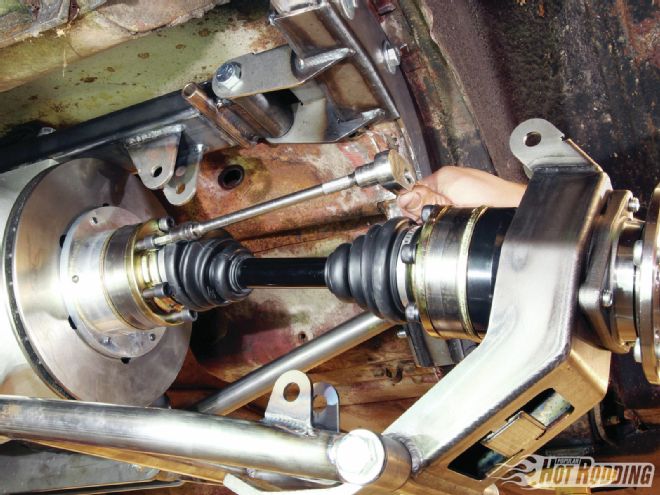 The whole assembly goes in at once by sliding the halfshaft into the upright with a little white lithium grease and bolting it in. These outer bolts need to be torqued to 180 ft-lb, but it’s best to wait until the brake system is installed and bled. The recessed side of the rotor assembly faces the axle stub and the halfshaft swings up and bolts to it at 57 ft-lb.
 The Wilwood brake calipers can now be slid into place on the mounting brackets with the ⅜-inch Grade 8 bolts. Shims are included to center the caliper onto the rotor. It’s a good idea to install your brake line fittings and parking brake cables before applying thread locker and torquing the caliper bolts.
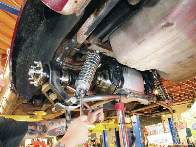 The upper links for the uprights can now be installed with the spacers on either side of the rod ends. The coilovers should be compressed to an initial free length of 12 inches to set the lower control arms and halfshafts at parallel. The upper coilover bolts will have to be slid in through the trunk access holes. After the coilovers are torqued down, the access hole covers can be installed from inside the trunk with the self-tapping screws.
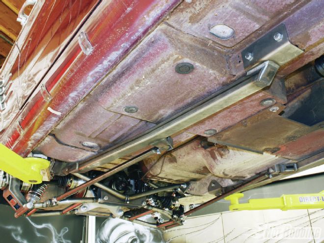 The very last step is installing the subframe connectors and strut rods. The rear mounting point for the subframe connector is the factory leaf-spring mounting point. After bolting it into place there, the subframe is swung up into place and the drilling location for the front mount is marked. Once the subframe is bolted into place, the adjustable end of the strut rod is attached to the upright, and the nonadjustable side to the subframe.
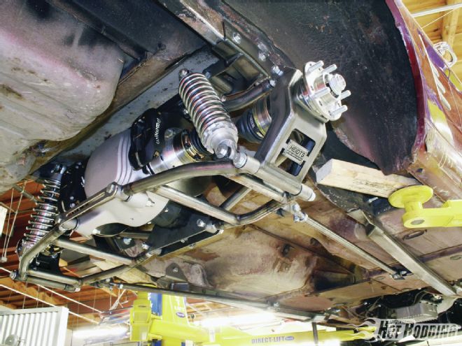 It took 47 years, but thanks to Heidts this 1966 convertible is independently sprung on all four corners and will have the true sports car ride and handling it was robbed of back in the 1960s.