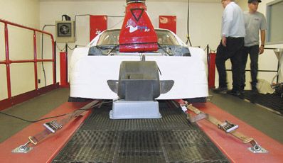
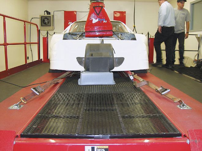
 With the car strapped down for business, we are about to discover a few things about horsepower and friction loss. The well-financed Winston Cup teams have their own chassis dynos and use them often. It is rare when we outsiders can utilize this kind of machinery to increase our know-ledge of short-track racing technology.
It was exciting news. Gerald Williams of Mid-State Machine called and informed us he had secured a dyno for a day. It was located at the Statesville, North Carolina, shop owned by the legen-dary Winston Cup team owner Travis Carter. Not only did we have the use of the dyno, we also secured an experienced technician, Chris Robinson, who works with Yates Racing as an engine and chassis dyno specialist. We were able to observe how these chassis dynamo-meters work and how we could use them to learn about how the engine output to the rear wheels could be enhanced.
The dyno we were using was a Dynojet Model 248, the same one used to monitor the Winston Cup cars. NASCAR began using the chassis dyno several years ago to keep track of the horsepower output of the teams to make sure no one was getting too far ahead of the other teams. A sudden jump in horsepower could indicate the use of illegal parts or procedures.
The device is also used by other sanctioning bodies to enforce horsepower limits. In those series, you are allowed to modify your engine any way you want, but are not allowed to exceed a maximum horsepower set by the rules. The officials let the teams use the chassis dyno, for a nominal fee, before they race to ensure they have not accidentally exceeded the limits of power. After the race, the top finishers must go on the dyno to make sure they are still within the power limits. That is a very simple and cost-effective way to keep the competition even, related to engine output, for any racing series.
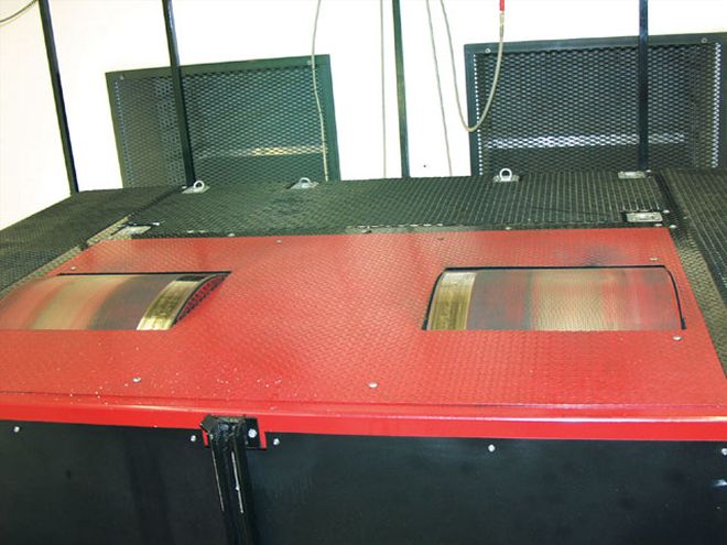 The rear wheels rest on 48-inch weighted rollers. Sensors monitor the rate of increase or decrease in speed of the rollers to measure horsepower. This system closely resembles the loads the powertrain experiences under real racetrack conditions.
Our goal for our chassis dyno test was to learn how these sessions are performed and to get familiar with the use of this type of machine so we might develop experiments and comparisons for short-track racing. We also wanted to do a rear differential comparison as well as play with pinion angles to see if there was any advantage there.
With this machine, we could determine both the maximum raw horsepower output of the engine measured at the rear wheels and also how much of that horsepower was used to turn the standard quick-change rear end that was fitted with standard bearings and seals. Once we tallied that data, we would then install a low friction differential that is called a Tiger rear end. This unit utilizes low friction bearings and seals and has polished gear surfaces along with some lightweight internal parts.
The first goal was to determine the significance of the reduction in parasitic loss compared to the added effort and added cost of production for the Tiger unit. We were to compare not only output horsepower numbers, but equally important, the coast-down horsepower figures that tell us how much of the raw horsepower is needed to turn the differential at various speeds.
 Travis Carter, longtime Winston Cup owner, seems more interested in the front-end geometry than horsepower. He was in the process of setting up his son Matt's Late Model car for a Saturday night race at Hickory Speedway.
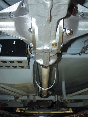
Measured A second goal, and one that has interested me for some time, was to experiment with various pinion angles to see how much power loss resulted from excess pinion and transmission angle. I had imagined a substantial loss due to this effect and I was about to get a lesson in mechanics. True pinion angle is the measurement of the side view angular difference between the driveshaft and the pinion, the driveshaft and the transmission output shaft, as well as the angles created from a top view alignment of the transmission and the pinion shaft.
Some cars, especially the offset chassis type of cars, have a significant misalignment of the transmission and the pinion. I have measured 1 1/2 inch of difference in alignment with the transmission output shaft being to the left (driver's view) of the pinion shaft. For a car with a 45-inch driveshaft measured from center to center of the U-joints, that is 1.91 degrees of angle at each end of the driveshaft. That alone would be the same as having 4 degrees of pinion angle if the driveshaft, transmission, and pinion all lined up.
With those goals established, we began to prepare the car. The choice of cars was a NASCAR Late Model with a 350 engine running a two-barrel carburetor. The crew consisted of Chris, the dyno driver; Gerald Williams; Gerald's son, Tim, who "drove" the car (as well as raced this particular car); and mechanic Wayne Ingram.
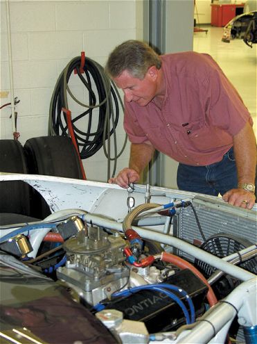
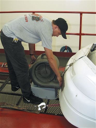 Wayne attaches a blower to the front of the car so that air can be circulated through the radiator to cool the engine during the many runs.
We first had to install rear tires that were the same circumference as the normal right-rear tire (stagger would cause big problems on the dyno) and air them up to 40 pounds to keep wheel hop to a minimum during run-up. We also moved the front of the third link up so that there was minimum angle to eliminate any anti-squat properties. This would help us maintain the ride height while under power so the pinion angles would stay consistent throughout each run.
Once the car was positioned on the dyno and strapped down securely, we positioned the ambient air inlet in front of the air cleaner. Because we needed to eliminate the possibility of heated air coming from the headers from entering the air cleaner and carburetor, we changed that setup and removed the end of the fresh air inlet hose and the air cleaner so that the outside air dumped directly into the open carburetor.
The initial runs showed this engine was somewhat down on horsepower compared to similar engines that had been run on this dyno. The crew had suspected that for some time. The goals would not need to change because of the shortage of horsepower. Gains or losses are not dependant on the exact amount of horsepower, only percentages of loss or gain as changes are made.
 The test car was a NASCAR-legal Late Model type that mostly race in and around the mid-eastern portion of the U.S., including North Carolina, South Carolina, Georgia, Tennessee, and Virginia. These are perimeter-type cars with no offset in the chassis. For this reason, the driveshaft did line up nicely with only a 1/4-inch difference in alignment.
As we began the first series of runs, Tim's attempt to come up through the gears was a little rough as the car bucked on the rollers. We then repositioned the rear tie-down straps to pull down and control the vertical movement of the car rather than just pulling backwards. The take-offs were a little smoother. The goal was to get the car into Fourth gear and run it for a while to get all of the driveline parts and lubricants warmed up. Tim finally learned that if he started off in Third gear, the take-off was much smoother.
For each run-up, Tim would signal that the starting engine temperature was reached and then apply full throttle. As the lower and upper limits of rpm were reached, Chris would press a button to start and to stop recording the run. When the engine reached the maximum rpm, Tim would let off the gas, push in the clutch and quickly knock the car out of gear. The dyno recorded the horsepower as the rpm climbed and then recorded the horsepower during the coastdown, which actually showed a negative number on the chart. We were shooting to record the maximum horsepower output of the engine on run-up and then the amount of resistance at two speed intervals, 85 mph and 100 mph while the car was "coasting", stopping the "run" at around 80 mph.
There were several conditions that were out of our control and every scientific experiment requires keeping track and controlling all variables. Since we are racers and not scientists, there were admittedly some influences taking place that we could not measure or control. These were a) transmission oil temperature, b) rear end oil temperature, c) all bearing temperatures including the U-joints and wheel bearings, along with their respective lubricants, d) engine oil temperature (although we did control the water temperature which roughly correlates to the oil temperature), and e) the heating and expanding of metal parts due to elevated temperatures as each of the three-run sessions progressed.
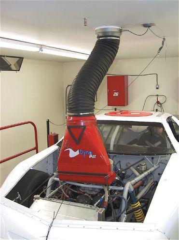 The inlet on the left is one that is used with the Winston Cup car's air cleaner box. The car's air box is turned around and fitted tightly to the fresh air supply fixture.
Chris informed us that when running a Winston Cup chassis dyno test, they monitor the rear end, transmission, and engine oil temperatures and try to keep them as consistent as possible for each run so that they are comparing apples to apples. We did not have the equipment needed to do that, so we tried to compensate by doing the three-run sessions and spacing the runs equally so that any increase in heating was consistent for each set of runs.
We were able to monitor the outside air temperature (coming into the carburetor) as well as the barometric pressure and humidity, which all stayed very constant throughout the test. Chris commented that the horsepower numbers were well within an acceptable backup percentage.
We began the test with the "old" style rear end installed with standard bearings and seals. We ran several stabilization runs to get the driver familiar with the procedure. He would take the car to Fourth gear and then hold the rpm at around 4,000 until the water temperature reached 140 degrees. Once the temperature was there, he would radio Chris and then start the run. Full throttle was then applied and Chris would hit a button that started the computerized recording of the run at 4,500 rpm. He would once again hit the button to stop the recording at 6,000 rpm. For this motor, with the small carburetor, peak horsepower was reached at around 4,800 rpm and we were interested in coast-down figures at 85 mph and 100 mph. Those speeds fit that rpm range.
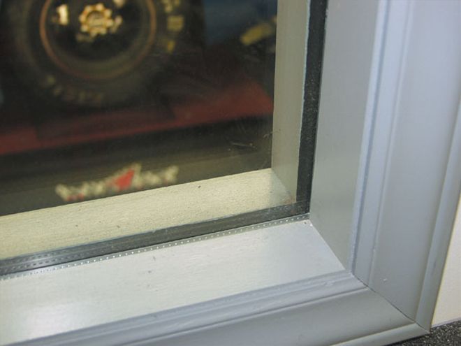 For safety reasons, we were separated from the car and dyno by 3/4-inch-thick bulletproof glass, just in case some-thing "blew up." When this dyno is used with a high-horsepower Winston Cup engine installed, the power can exceed 750 hp. While under load, these powerful engines can become a hand grenade of sorts in a hurry.
Once Tim was comfortable, we ran five sets of three runs, averaging the maximum horsepower at the rear wheels as well as the amount of horsepower of resistance during coast down at speeds of 85 and 100 mph. The numbers for resistance show as negative horsepower figures due to the dyno measuring "backwards" from the way it measures output. The average horsepower for the runs using the standard quick-change rear end was 283.88 hp with coast-down averages of 16.70 hp at 85 mph and 23.93 hp at 100 mph.
We then removed that rear end and installed a quick-change that had a different type of low friction bearings and low friction seals. Almost all of the internal surfaces were polished, especially the gear faces. The car was once again positioned on the dyno and all running gear angles (transmission, drive shaft, and pinion) were returned to the same as in the previous runs. The first run we made with the new differential told us that we had stumbled upon something significant.
After a few warm-up runs to heat the engine, transmission lube, U-joint bearings, rear-end lube, and axle bearings as in the first runs, we did the first three-run set. We were surprised to see a significant gain in maximum horsepower as well as a loss in coast-down resistance of around 50 percent. We ran five series of three dyno runs, just like the first test with the stand quick-change, and averaged the numbers. The maximum horsepower was 298.13 and the coast-down numbers were 8.4 hp at 85 mph and 11.42 hp at 100 mph.
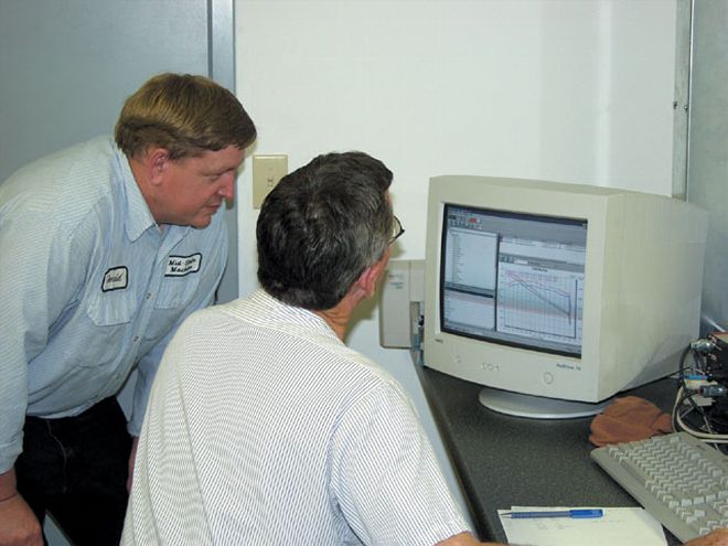 Gerald and Chris go over the data from one of the runs. We were concerned that the conditions stayed the same from run to run so that we could effectively compare the numbers. Chris told us that from his experience, he felt the entire session was run under favorable conditions and had yielded believable data.
We gained an average of 14.25 hp overall and reduced the parasitic losses through the rear end by 50 percent at 85 mph and 52 percent at 100 mph. We ran this test with as much control over the environment as possible. With the right resources, we could have monitored the various temperatures more closely to better substantiate the results. Chris felt we did all we could given the time constraints and equipment available to short-track guys like us, so the numbers were well within a believable range. He felt that we had indeed recorded some meaningful data.
At the end of the last set of runs, we experimented with pinion angles and actually learned some interesting facts. Our Winston Cup consulting engineer, Terry Satchell, told us the most important factor in pinion/driveshaft/transmission angles was to have equal angles at each end of the driveshaft. This would be the most efficient design, yielding less loss of horsepower from bearing bind at the chassis attitude that is the result of the car accelerating. What we discovered was not what we had expected.
We did experience a slight gain in horsepower due to changes in the pinion angle. We could not change the transmission angle, so all of the changes were to the pinion. We recorded a run at zero pinion angle and then at 10 degrees of pinion angle. We expected a loss in horsepower at the greater pinion angle, but actually experienced a net gain in horsepower. This was very confusing until we thought about what Terry had said. When the pinion was at 10 degrees, the angles at the ends of the driveshaft were opposite and closer to equal. This was a better situation providing less resistance than when the pinion was at zero degrees with the transmission angle at a much different angle.
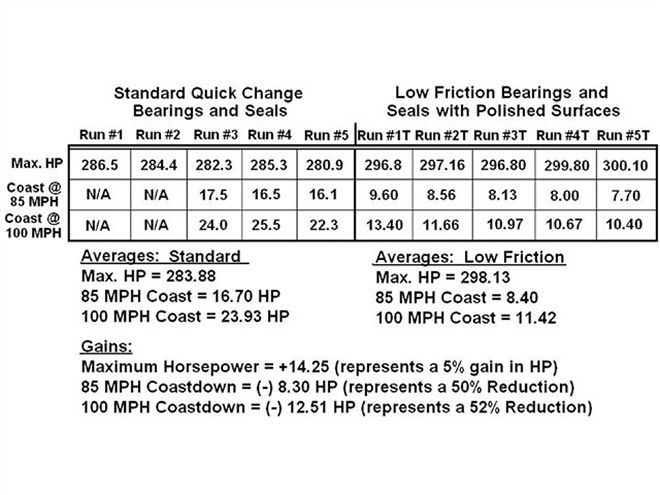 The chart shows the average results of each set of runs for each rear-end configuration. Note how close the horsepower numbers are within each five set of runs. There is less than one percent of difference between each set of three runs. The gains are noted from maximum horsepower and also horsepower needed to turn the differential.
Most racers only measure the pinion angle relative to the ground when they should measure both the pinion and transmission angles relative to the driveshaft. The angles should be equal and either opposite or in the same direction to help eliminate vibration and drag through the U-joints.
This yields more rear wheel horsepower as well as longer component life due to vibration-free movement as the bearings rotate. You should always maintain some amount of pinion (driveshaft to pinion and transmission shaft) angle so that the needle bearings in the U-joints will be loaded. The slight angle forces them to rotate, which helps keep them lubricated. Running zero angle in the U-joints will ruin the needle bearings in a hurry. Maintain two to four degrees of angle (transmission to driveshaft and driveshaft to pinion) at each of the U-joints.
If all of your handling problems have been sorted out and the engine is up to horsepower with all of your competitors, it may well be time to take a look at horsepower losses that may be robbing you of power at the rear wheels. Do some dyno time once in a while to make sure your driveline system is up to par. Reducing power loss through the driveline is all part of putting together that total winning package.
(Special thanks to Travis Carter for use of the dyno and Robert Yates Racing for the services of Chris Robinson).