The front roll center location is extremely important to the performance of your race car chassis. Its position will determine how your suspension will react to the forces and motions caused by negotiating a turn.
There are two reasons why we need to know the location of the roll center. One is to help determine the camber change characteristics, the other is to help determine how the dynamic forces will influence the handling of the race car. The height of the roll center (above or below the ground) affects the camber change characteristics. The position left or right of the centerline of the car will determine how the suspension will react to the dynamic forces which will cause the car to roll in the turns.
Let's measure a race car together so that we can analyze a typical double A- arm front-suspension system. We will use these measurements in a two-dimensional (height and width) geometry software program. We want to determine where the roll center is located in order to determine how that location influences the geometric and dynamic characteristics of our race car. It's important to accurately measure these points if you expect to get accurate information back about the position of your roll center. Here are some helpful instructions on how to correctly measure the suspension points on your race car.
The first consideration is to find a level floor on which to measure. Professional teams use a surface plate made of thick machined steel. Not all of us are so fortunate. So, instead, find a portion of your garage floor that is level. We only need an area that measures about 65x20 inches to position the front suspension over.
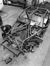
The measurements are much easier to determine if the engine is out of the car. If you can't get them while the engine is out of the car, try to block the car up at the chassis corners in order to provide easy access to the lower-suspension mounting points. Use the same distance to block up at each corner. Remember to support the car safely and use jackstands as backups in case the car shifts while someone is under it. You can't use too much caution here. A good distance to block up is 10 inches, because this is an easy number to subtract from your initial height measurements. It's a good idea to record the actual distance the points are from the floor if the car was at ride height, to avoid confusion later on.
We need to establish a centerline of the chassis. To correctly analyze the roll center, which influences the camber change characteristics and dynamic properties of the chassis, we want to use a centerline which is halfway between the tire contact patches. This is the centerline which the car will feel as the forces react on it in the turns. It is important for us to know where our roll center is in relation to this centerline.
Ball-joint measurements will be easier to take if the wheel is removed. Here is a method that keeps the spindle in the correct position after the wheel is removed. Before you block the car up, measure and record the length of each front shock from bolt to bolt, with the car at ride height and the race weight in it (including all fluids and the driver). Then, block the car up as explained above and remove the shocks and springs (either the spring/shock combo in a coilover configuration or the shock and separate spring in a stock-type big-spring car). In place of the shocks, insert a piece of tubing or strap metal which has two holes drilled in the ends exactly the same diameter and distance apart as the shock lengths you measured.
Mark the center on the bottom of each tire and measure between them. Place a mark on the floor halfway between these two tire centers. Repeat this procedure for the rear tires. Then, snap a chalk line over these two centerline points, front to rear, to produce the centerline you will measure the width of each point to. Now you can remove the wheels, and the spindle will be at the exact same vertical position as it was when the car was at ride height.
Now that the car is positioned so that we can get to the chassis points, we need to determine the center of rotation for each point. This is easy for Heim joints or mono ball joints, but many race cars use the OEM-type ball joints. The center of rotation is not obvious for this type of ball joint. We'll need a little help. Do not eyeball these points and guess at the location. Instead, use the information supplied by each manufacturer. Your supplier should be able to get you this information. We've included centerline diagrams on two popular ball joints. Be persistent and get this information before you start. Your roll center location will only be as accurate as your measurements.
Now, we're ready to measure. First, determine the height of each point. Measure from the floor to the center of rotation for each point. Remember to subtract the distance you blocked the chassis up from ride height from this measurement. We want a number which represents the height of each point as if the car were at ride height with all of the race weight on it.
Getting the true height of the upper chassis mounts and ball joints is going to be difficult. You won't be able to measure at right angles to the floor directly to these points. There are suspension components in the way. So, we need to be innovative. Again, do not eyeball the measurements to these points. Use a small level to extend the height of the center of rotation out and beyond the suspension components so an accurate measurement can be taken. You need a helper to get this done right.
To measure the lower control-arm chassis points, use the front chassis mounting points on the chassis. Whether you have a strut-type system or an OEM-type lower control arm, you need to use the front chassis mounting point for a two-dimensional roll center analysis.
Now that you have recorded the heights of each point, measure the width each point lies from the centerline of the car. Use a plumb bob to project the lateral center of rotation down to the floor. Place a piece of masking tape on the floor to mark on. Put a crows foot mark on the tape and circle it so that it is easy to find. Measure from each point to the chalk line which marks the centerline of the race car. For this measurement, make sure the tape measure is at the right angles to the chalk line. We want the shortest distance.
Once all of the points are measured and recorded, we enter this data in the geometry software program. For this example, we use the new double A-arm geometry software produced by Chassis R&D. This Windows-based software is easy to use as it shows a picture of the cross section of the chassis. Each height and width location is entered next to the picture point on the chassis diagram.
The software also allows you to quickly calculate the location of the roll centers and make changes to that location easily. The display shows the existing control-arm angles, both upper and lower, as well as the lengths of the upper control arms.
To make the changes to the roll center locations, simply type in the new control-arm angles or upper control-arm lengths and recompute the roll center locations. The program automatically calculates the new chassis mounting-point locations and tells you how far each one has moved from the original mounting points in the computer, should you decide to change them.
It's important to look at the control-arm angles which will determine the roll center location height and width (both static and dynamic). To reposition the roll centers, we must change these control-arm angles. For example, if we increase the right upper control-arm angle and/or decrease the left upper control-arm angle, we will move the roll center to the right from its original position. If we increase both the upper control-arm angles, we increase the roll center height.
The program calculates the tire camber angles after the chassis dives and rolls, and the kingpin angles of our spindles. Making changes to the upper control-arm lengths affects the amount of tire camber change when the chassis dives and rolls.
Additional pages in this software program contain provisions for calculating center of gravity, height, and wheel weights, when the user knows the percents he or she wants and the total vehicle weight.
Remember, the roll center width affects how the dynamic forces affect the front of the chassis and the height affects the amount of camber change that occurs during dive and roll. When you know where your roll center is located, you can better control how your race car will perform.