In the recent past, we have talked about racers building their race engines themselves, much like almost everyone did 40 years ago. Many of the problems the builders ran into way back then have been almost eliminated. The parts we get from the suppliers are better than we would have gotten from a qualified machine shop after a lot of work back in the day.
So, we decided to build the race engine for our Modified project car raced by Dick Anderson and document the process. To oversee this endeavor, we enlisted veteran Florida engine guru Byron Koury Sr. and his crew, Byron Jr. and David Thorne, at their Deland, Florida, engine workshop. We want to show that if a chassis guy like me can build a race motor and learn the process, then just about anyone can.
I will be doing all of the work myself and Byron will supply the knowledge and expertise I will need to end up with a product we can race with. Once all of the work is done, we will be running the engine on his dyno and testing it to record the horsepower and torque values.
I have previous experience building a few engines and the processes I learned in my teens mostly still apply today. We will be interjecting some modern knowledge that can help keep your project from going wrong. It’s all about the process, whether we are setting up the chassis or building a motor.
What this build should do for you, we hope, is demonstrate how easy it is in this modern day to do this work using the CNC parts that provide tighter manufacturing tolerances. Even novice builders can now order the correct parts and assemble the engine literally in your garage with minimal tools.
There will be some specialized equipment you will need, but much of it you probably already have. This will be a multi-part series in order to properly explain the entire process. So, let’s get started with this first phase.
If you are new to this build game, talk to your supplier about which parts you will need for your particular application. Your engine will need to meet the rules that have been established at the track or tracks that you will run. You want the parts that will produce the most power possible under the current rules package.
You will need the block, crankshaft, camshaft, pistons, rods, bearings for the cam, crank and rods, heads with valves, rockers, push rods and valvesprings, lifters, timing chain kit, gasket kit, and a bolt/stud kit. These parts will complete the short-block qualifying process. We’ll list other parts that will complete our motor later on.
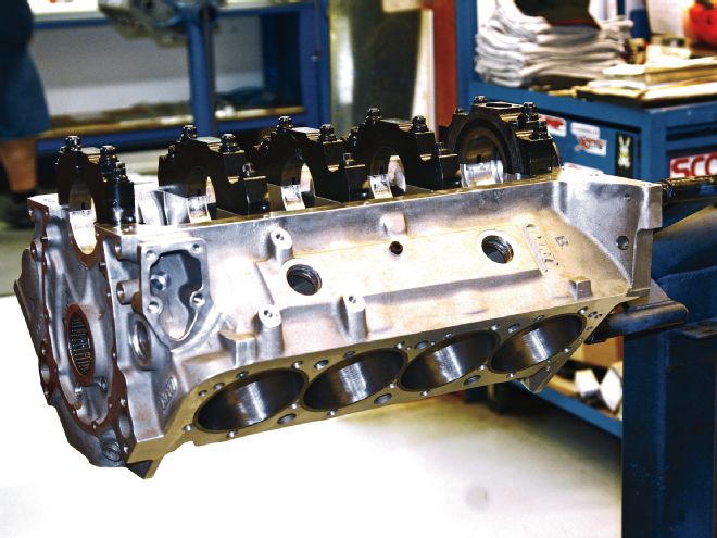
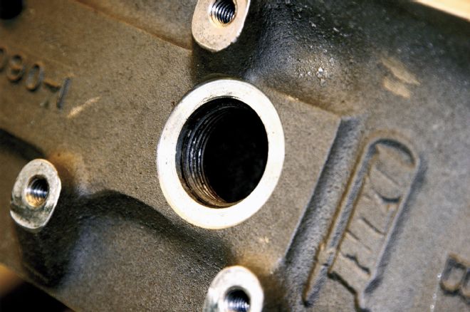 We started with a Dart block that had been used before, but was in great shape and prepared by Joe Rhyne of Rhyne Competition Racing Engines, a reputable engine builder in Gary, IN. We first washed the block and removed any residual pieces of machining that might remain as well as any heavy oils or solvents. Once we are sure we have a clean and ready-to-work-with block, we check all of the threaded holes in the block. This is to make sure that the threads are in good working order. If we find a bad thread, now is the time to chase it with a tap, which will create more small pieces of loose material that will need to be washed off before we begin to work with the block.
First off, we would recommend that you work with a modern block from an OEM or one that was produced by a reputable aftermarket supplier of racing engine blocks. All of those will have been machined to very close tolerances and need little, if any, modifications.
In other words, the block will have close tolerances for cam, crankshaft, and piston bores, be aligned correctly through the cam tunnel and crank journals, and the piston bores will be perpendicular to the crankshaft. For our build we used a block from Dart, a leading supplier of race-quality blocks.
The first thing we do is clean the block thoroughly and then qualify the dimensions. In this part 1, we are not doing the final assembly of the motor, just making sure all of the parts fit and have sufficient clearances. Once you are sure there are no leftover shavings or oils left over from manufacturing, place the bare engine block on your engine stand. If you don’t have one, buy a good used or new one. It will be used quite a bit during the build.
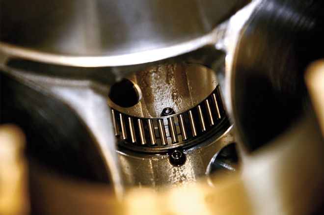 Our block came to us with roller cam bearings installed. Although an extra cost item because the cam tunnel needs to be bored out, we recommend using these bearings in higher horsepower engines with high lift cams and high ratio rockers. The loads on the cam are very high, pushing those stiff valvesprings using high lift and longer duration cams. These roller bearings are pinned with small socket head bolts threaded into the block on each side of the bearings.
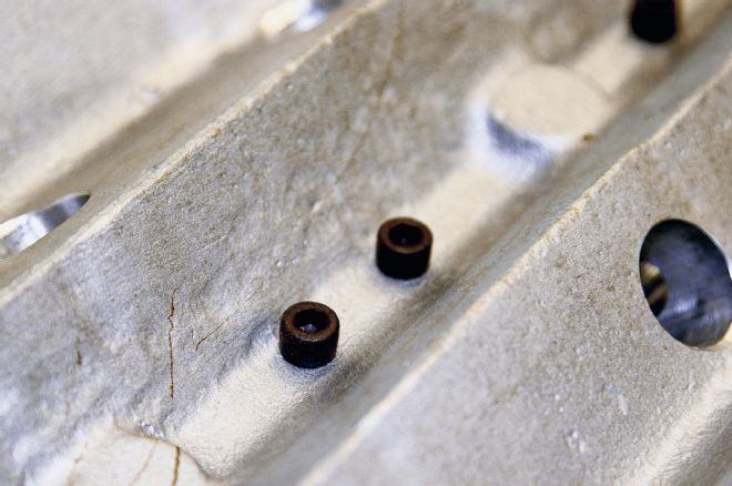 Here we see the other end of the socket head bolts that pin the roller cam bearings. You drill through the bottom side of the block under the cam tunnel being careful to get the holes precisely on each side of the bearing. Then thread the holes and screw in the socket head bolts. These bearings are known to “walk” during heavy use.
We want to note here that whenever you are assembling parts for any reason, always lubricate them with assembly oil. When we mock up the crank and pistons for clearance checks, we lubricate all of those parts that will come in contact with other parts of the motor.
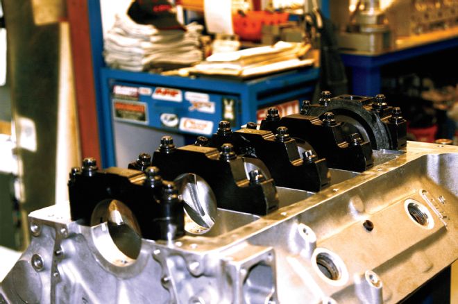
We need to know the sizes and if all of the bores for each component are the same within a very close tolerance. Turn the block upside down and bolt on the main caps finger tight. Torque the studs (or bolts if that is the case) starting with the two inside (for a four-bolt main) and then the outside for each cap. Torque each stud to 50 lb-ft first going back and forth in increments between each stud in each cap until you reach the limit on all of the caps. Then go back through each cap and tighten the 7/16-inch studs in the four smaller front caps and the rear cap to 65 lb-ft and the larger 1/2-inch rear cap studs to 85 lb-ft. Tighten in the order we discussed.
Now would be a good time to number each main bearing and rod cap starting at the front of the engine. You can use an etching tool, but never stamp the main or rod caps. With the number read from standing at the front of the engine block, the first cap would be #1, second #2, then back to the last main cap being #5, and obviously the last rod cap being #8. We will want to return each cap to the same location and orientation each time we re-install the crank caps.
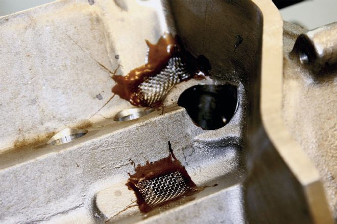 Another thing you can do to prevent extended damage should a part of your valvetrain fail is to epoxy stainless steel screens over the oil drain holes in the tray part of the block where the valvetrain oil flows back to the bottom of the block. This way, if a rocker or other part of the valvetrain on the head fails, these screens will catch the larger pieces before they can make it to the oil pan or sump pump in a dry-sump motor.
Once all of the main bearing caps have been torqued to spec, measure the bore for each bearing and record the sizes. These all need to be within +/- 0.0005 of each other. Measure the vertical dimension, then at 45 degrees each way for three measurements to determine if the hole is round. Variances in the three measurements of up to a half a thousandth is OK for now. Our average sizes for all of the bearing bores were about 0.0015 over.
Now, remove the caps and place the bearing halves into the block and the caps and bolt and torque the caps back onto the block just like we explained before. Once all of the caps are secure, measure the bearing bores in the same three places. Record these measurements.
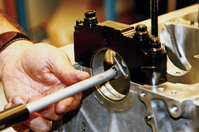
Next we need to measure the main and rod journal sizes on the crankshaft and then do the same bore measurements for the rods, first bolting on the rod caps, torque and measure the bore, and then install the bearings and measure the bearing bore. Again, record all of the measurements. The normal clearance for both the crank and the rod bearings is 0.0025 to 0.003 inch.
Measure your piston cylinder bore diameters in all eight cylinders at three places like what we did for the crank bearing bores. Lay out the pistons and rods and arrange them to match each cylinder. Install the rods into the pistons along with spacers, pins, and retainers. The rods may be oriented a certain way, so be sure to get this right. Refer to the included instructions that come with the pistons, or call your piston manufacturer.
Now would be a good time to mark and number each piston rod cap corresponding to the piston numbering system for the block type you are using. You can best use an etching tool like an electric pencil. Do not stamp the caps. Make sure the orientation of the piston corresponds to the valves, i.e. that the intake (larger) valve is over the larger cut in the piston. Each piston is made to correspond to the valve arrangement for each cylinder.
Now measure each piston diameter at a point below the ring grooves near the skirt and record those sizes. The difference in size between the piston and the cylinder is divided by 2 to get the piston to wall clearance. The acceptable clearance for piston to cylinder wall is according to the manufacturer’s recommendations, but usually falls within the range of 0.0035 to 0.010 inch.
 Once we have cleaned and prepared the block, the next step is to qualify the block. This process involves checking all the bore sizes and clearances before final assembly. The first step is to check the sizes for the main bearings. We install the main caps without the bearings and torque them in steps. We torque the middle two studs in each main first, then the outer two for each cap. Tighten the studs in increments going back and forth between each pair. Start out torqueing to 50 lb-ft on all of the studs and then to 65 lb-ft for the smaller 7/16-inch studs and 85 lb-ft for the larger 1/2-inch rear cap studs.
Now we are ready to check the piston to deck height. This is a check to see if the piston, when at its top dead center, will protrude higher than the block deck or be down into the bore. First, install the crank with bearings and tighten to snug. Choose either of the front pistons and put the bearings in the corresponding rod and cap for that piston. Carefully lower the piston into the cylinder, making sure the rod end will not mar the cylinder and attach the rod cap to snug tightness.
For flat-top pistons, with the block rotated so that the piston is at top dead center, place a true flat level across the block and across the highest part of the piston. If the level contacts the block on both sides, then the piston is either level with the block deck or down into the bore. If the piston is higher than the deck, we can measure how much. Use two gap gauges, one on each side with the same thickness, to determine how far up it protrudes.
Many rules state that when using flat-top pistons, no part of the piston can be higher than the block deck. Our pistons were 0.006-inch higher than the deck, so we had to turn the pistons in the lathe to take off that amount. This is probably because this block was used before and the deck may have been trued by milling off 0.010 inch or so. With a new block, this should not be a problem, but to be sure, we need to check it.
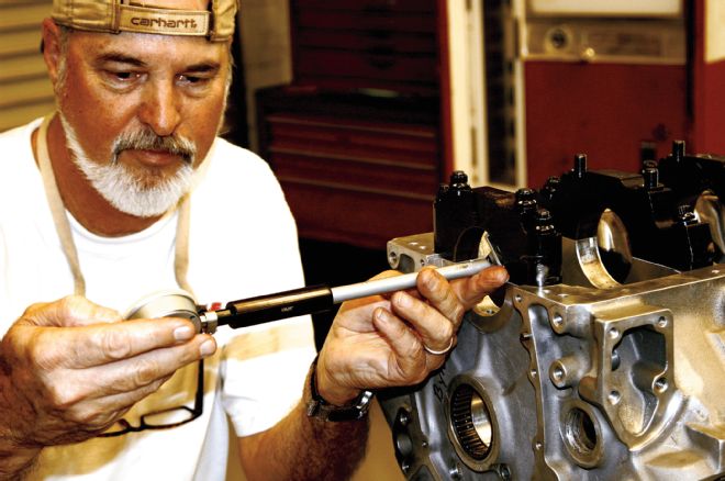 Next we use a bore gauge to measure each main bearing bore. We first set our gauge to 0 at the standard bore size for the bearing we will use. Then we see how the actual main bearing bore checks out against that size. We check our bores in three places, vertical, left 45 degrees, and then right 45 degrees. Our holes were consistently 0.0015 to 0.0018 larger.
We need to set our rocker arm heights before moving on. To do this, we need to assemble the heads by installing the valves, springs with retainers and retainer clips, rocker studs or rocker shaft if used, and the rocker arms. You will need a valvespring installation tool to compress the spring in order to get the valvespring retainers in place and clips installed.
We used a rocker shaft for our build so we need to adjust the height of that shaft to ensure proper rocker arm geometry. In this same issue of CT, we presented an explanation of proper valvetrain geometry and what that entails. Here, we put that to use.
 After measuring the main bearing bore sizes, we install the bearings, re-torque the main cap studs, and re-measure the bore size inside the bearings. The size was correct and we had very little variation between bearings. If all of that works out, then remove the caps and install the crankshaft and torque the studs. However, we still need to do some more checking in our qualifying process.
Our block had roller cam bearings already installed, and we recommend using those when possible. The cam tunnel will need to be bored out at extra cost, but for higher horsepower engines, it is a good idea. You will need to install your cam bearings before moving on.
Now, install the cam in the block along with the timing sprocket and chain, make sure the crank and cam are properly aligned and degreed for proper cam timing. See our sidebar for that process. Also, install one head over the previously installed piston and the two lifters and push rods for those rocker arms. With the piston positioned all of the way down, adjust the valve lash for each valve. While rotating the crank, note how the rocker tip moves across the valve stem on the valve closest to the outside.
We want the rocker tip to start just inside (toward the rocker stud) the center of the stem and then at half lift move just past the center of the stem. Upon full lift, the rocker tip should move back toward the rocker stud to the position it was at rest before lift.
If this is not the case, we need to shim or otherwise position the rockers up or down until we achieve this position of the tip of the rocker to the valve stem. The amount we shim will be the same across all rockers and for the entire rocker shaft. This process is one of the finer points of engine building and just bolting on the rockers and not checking them might not yield the best performance or good endurance.
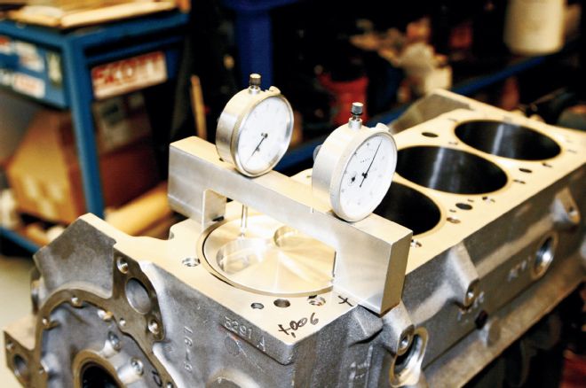 It is important to know how close our valves will come to the piston as the engine is run. To do this, we install one piston onto the crank and run it up to its top dead center. We used a specially prepared twin gauge tool that we zero on a flat surface and then read to determine if the piston is above or below the block deck. You can use a known straight surface or edge of a square and visually check to see if there is space between the piston and the edge, or if the edge rocks on the block and shows that the piston is above the block. Use two feeler gauges to measure the amount the piston is above the deck. If this is the case, you may need to have the pistons cut down to meet the rules that don’t allow any portion of the piston to be above the block.
The next step in making sure all of the parts are a good fit is to check the valve to piston clearance. We do this by placing a piece of putty into the valve relief cutouts in the same piston we checked the deck clearance with. Remove the head we just installed to check our valvetrain geometry. We need to place Play-Doh putty into the valve cutouts in the piston “dome” flush with the highest part of the piston. Lubricate the putty with oil so that it will not stick to the valves.
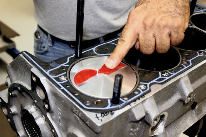 Our next step is to check the valve to piston clearance. The heads must be assembled with the valvetrain parts installed and the cam installed and degreed in, in order to complete this phase. Read the body text to learn the process of setting the correct valvetrain geometry before we start this process. Once the rockers are properly positioned, remove the heads and place putty (we used Play-Doh–brand kids putty) into the valve relief cuts in the piston. Just be sure to lubricate the putty so it does not stick to the valves. Now run the piston all of the way down in the bore and replace the head using a head gasket and tighten four of the head bolts. For this exercise, we don’t need to completely bolt and torque the head. We just need to hold it firmly in place. Also, replace the two push rods for this cylinder and set the valve lash to 0.
Reinstall the head without the gasket and snug tighten the head bolts. Now we need to carefully turn the crank 720 degrees being careful to stop if there is any hard resistance. If not, make several rotations then stop. Remove the head and visually look at the putty. The valves will have made an impression.
We can use a micrometer to measure the gap represented by the putty thickness both horizontally from the edge of the valve to the cutout and vertically from the face of the valve to the top of the piston. These clearances should be a minimum of 0.020 inch laterally for the back cut and vertically 0.0100 inch for the exhaust, and 0.080 inch for the intake valves. For engines designed to run above 7,500 to 8,000 rpm, those clearances should be 0.125-inch exhaust and 0.100-inch intake. If we do not have those clearances, the piston will need to be cut for proper relief.
For most applications, using parts made to work with each other, these clearances should be fine. You need to check and correct any tolerances that might not be sufficient mainly because the heads you are using might not exactly match the piston design you are using. Again, it’s always a good idea to know your clearances before bending a valve and destroying an entire engine.
The engine we are assembling is a departure from what you would normally expect to build to most rules packages. We will be running this engine in a pavement Modified class that allows a certain amount of freedom and creativity. Be that as it may, this process is just exactly what you should follow in building your motor, be it a spec motor or one that is more exotic in nature.
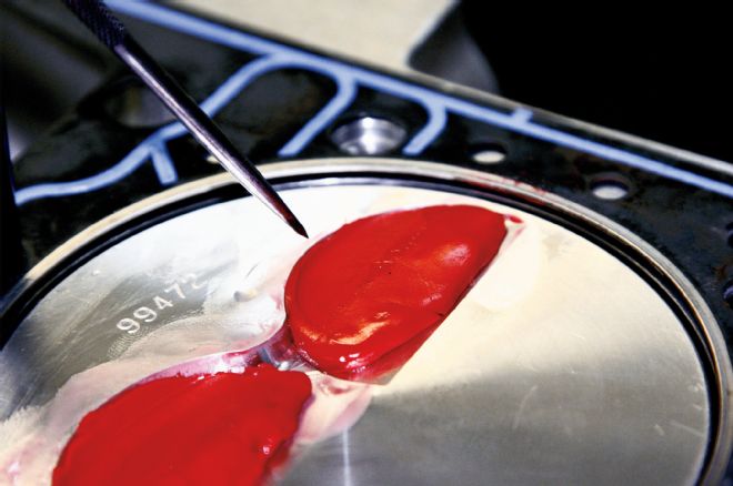 Rotate the crank through 720 degrees twice so that we are sure the intake and exhaust valves have been fully opened. This will leave an impression in the putty for each valve. We then remove the head and check visually where the valve moved in relation to the piston and valve relief cuts. We can measure the thickness of the remaining putty to know the exact clearances by cutting each one in half with a sharp knife. The lateral back cut clearance should be a minimum of 0.020 inch and the vertical clearance a minimum of 0.100-inch exhaust and 0.080-inch intake for engines running under 7,500 rpm. Add 0.020 inch to both for engines running over 7,500 rpm. In the event our clearance is too little, the piston would need to be cut so that there is plenty of room for the valve to operate.
This completes our process of qualifying the block by making sure the bore sizes are correct for the bearings used, that the bearing clearances are correct, the piston to cylinder wall clearance is OK, and that our piston height to the block deck is within the rules. We also know that our valves will clear the piston with plenty of room. Piston to valve contact is one of the primary reasons why valves bend, or break, and in doing so destroy a lot of hard work and cause a lot of expense.
In part 2 we will do the final assembly of the block detailing how to fit the parts, explain torque patterns, and other helpful information. That process should go fairly quick and we should be able to fire and dyno the engine at the end of that process.
When we install our cam, we need to go through a process to ensure it is phased correctly with the crankshaft. Here, I will use the instructions provided by COMP Cams, our cam supplier for this project. COMP has a camshaft degree kit available with all of the parts we will refer to, to assist you.
Install the crankshaft, number one piston and rod, a complete head with head gasket over the piston, and the camshaft and timing set. Make sure the timing marks on both the cam and crank gear are aligned per cam instructions. Install your lifters and push rods and set valve lash to 0.
Attach a pointer (use a stiff wire bolted to the block and bent into shape) to the block to use to mark and read the degree wheel.
Attach the degree wheel to the balancer and install onto the crankshaft. Rotate the crank to get the number one piston to near top dead center (TDC). Adjust the pointer to 0 on the degree wheel.
Turn the crank opposite of normal rotation approximately 20 degrees. Install the piston stop until it touches the piston. Turn the crank in the same direction until the piston again touches the piston stop. Record the degree reading on the wheel.
Turn the engine in the other direction until the piston again touches the stop. Record the degree reading. Remove the piston stop and move the crank to midway between the two readings. This is TDC of the number one piston. Without moving the crank, move the degree wheel or pointer to read 0 on the wheel.
Attach a dial indicator to a position above the intake valve retainer in line with the valve stem. Rotate the engine in the normal direction of rotation until the valve is at maximum lift. Now set 0 on the dial.
Back the crank (opposite direction of rotation) until the dial indicates 0.100-inch travel and then back in the direction of rotation to a reading of 0.050 inch. Record the degree wheel reading.
Continue to rotate the crank past max lift to 0.050 inch on the dial on the closing side of the cam. Record the degree wheel reading. Add those two readings and divide by 2. This will be the location in degrees before TDC of maximum lift and is the intake centerline. Reference back to your cam spec card to see if this is the recommended intake centerline.
If not, you may need to advance or retard the cam using either an offset crank key or an adjustable cam gear with offset bushings. When ordering your timing gear set, consider which you would like. The adjustable cam gear set offered by COMP Cams is very easy to use and saves a lot of time.