With the LS327 engine permanently mounted in our 1968 C10, I decided to start the fabrication process on the intercooler assembly. Since I knew I'd be sending out a handful of parts to Eddie Motorsports to have powdercoated once I finished, I wanted to get this portion wrapped up as soon as possible so that they could be out getting shot while I moved on to something else. It's this kind of thinking that sometimes gets me into trouble!
Originally, our plan was to route the inlet directly from the TorqStorm supercharger into the GM throttle body. This was obviously the simplest method as it only required a few bends and a short piece of straight tubing to get from the outlet on the supercharger to the throttle body at the front of the engine. With our projected estimate of 6-8 pounds of boost, this seemed like a logical idea. The more we discussed things, however, the more it became apparent that if we wanted to either add more boost to the mix or not run the risk of having to take timing out of the engine, we needed to find a way to cool the incoming charge.
The reason the incoming charge needs to be cooled is simple: superchargers create increased inlet temperatures. By compressing the incoming air to create more pressure or boost, heat is created. Adding a heated intake charge increases detonation problems, wear, and heat damage. All of which are the enemy of a high-performance engine. So, what we want to do is bring that increased inlet temp back down near where it would be for a naturally aspirated engine or perhaps even cooler.
To do so, we have three basic options:
An air-to-air intercooler, which cools the incoming charge by passing it through an aluminum intercooler that is mounted in the path of cool, fresh air. This is the simplest solution and is maintenance free.
An air-to-water intercooler, which cools the incoming charge by passing it through an aluminum intercooler that is cooled by water that is pumped via an electric pump from an external tank. This method involves a number of additional components, increased maintenance, and is the most complex.
Chemical cooling via water and/or methanol injection. This option introduces a water/methanol mixture into the inlet system to cool the incoming charge on the way to the combustion chamber. Like the air-to-water method, this system also requires a number of extra components including an external tank, pump, and a controller to determine when to inject the mixture.
Since our project is being built for street duty and not as a fulltime track rat, I opted to go with the simplest method, an air-to-air intercooler. Though not the easiest of the three to install, as it will require quite a bit of fabrication initially, once in place it will be completely self-sufficient.
When it came to picking out an intercooler to fit our project, we got with the guys at Vibrant Performance to discuss our needs. Based on our projected boost, horsepower and displacement, they recommended using their largest intercooler, which is good for nearly 900 horsepower. Featuring aluminum bar and plate construction for maximum cooling efficiency with minimal pressure drop, the 33x12-inch intercooler will just squeeze between the radiator core support and grille in the '68. To mate to the supercharger on one end and the throttle body on the other, Vibrant also provided a handful of 3-inch aluminum tubing bends as well as a few feet of straight tubing. TIG welded together, the inlet tract will be attached to the components using Vibrant four-ply reinforced silicone hump hose. These allow the engine to move while the intercooler remains solidly mounted without risk of cracking the aluminum inlet tract thanks to the hump hose's inherent ability to flex in the middle, or hump portion, more than a traditional silicone coupler.
Though simple in execution, the addition of a front-mounted intercooler isn't without its share of headaches, as there's just enough space for it to coexist in front of the A/C evaporator and the grille. The front valance will need to be reworked as will the lower grille opening and turn signals. This requires a bit of thought as the deletion of the front turn signals all of a sudden becomes not a problem of logistics, but of legality. Thankfully, there are a few solutions when it comes to moving them. The biggest hurdle I had to overcome was the fact that I had almost no previous experience TIG welding aluminum. Needless to say there was a steep learning curve when it came to welding the 1.5mm wall T6061 aluminum tubing. A few practice scraps and it was trial by fire; in the end I think it turned out pretty nice and my confidence when it comes to welding aluminum has definitely improved.
With the intercooler now providing adequate cooling to the incoming air to our LS327, I'm much more confident that the whole package is going to be able to perform above and beyond my expectations without falling victim to a short-sighted weak link.
 1. The first task is to mount the intercooler to the front of our ’68. To do so, it’s necessary to remove the front grille, bumper, and hood latch support. The lower valance is also loose to give us quick access to the framerails if need be.
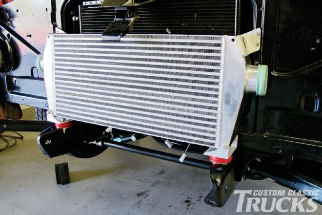
 2. Here’s the aluminum intercooler from Vibrant Performance that we’ll be using to cool the incoming inlet charge. It measures 33 inches from tank to tank, with a core dimension of 27x12-inches. At 3½ inches thick, it will just fit between the core support and the grille, but not without a few modifications.
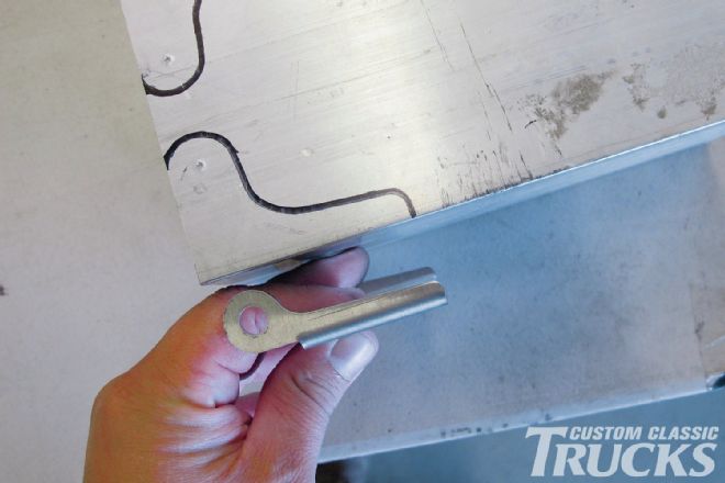 5. Not wanting to grind the weld down and risk possible failure of the joint, I opted to make a new set of mounts that will clear the welded area using a box section of aluminum tubing.
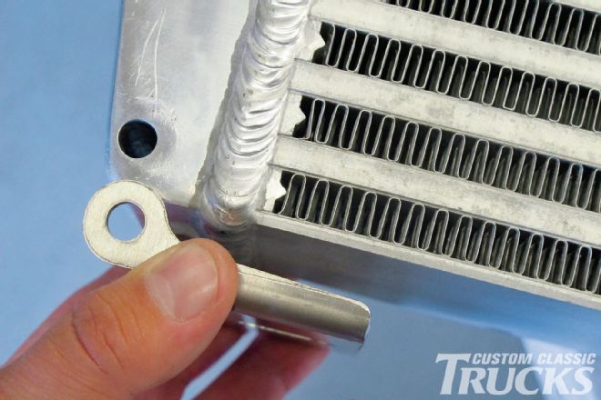
 3. Vibrant ships their intercoolers with these nice stainless steel mounts…
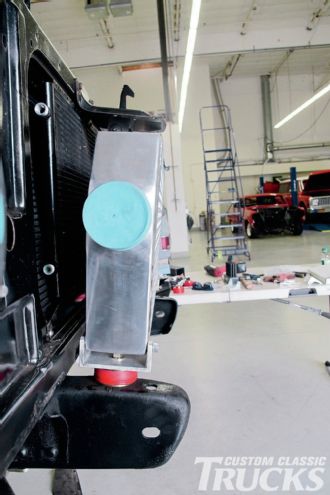
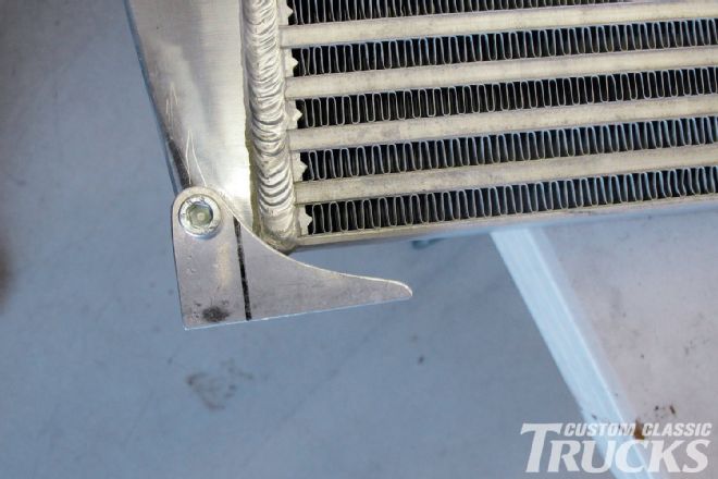 6. Here’s one mount being checked for fitment.
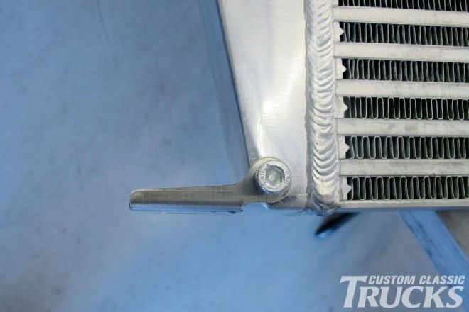
 4. …unfortunately, our application required the mounts to fall inside the width of the tank. Here, you can see that the mount would foul on the TIG weld that connects the tank to the core.
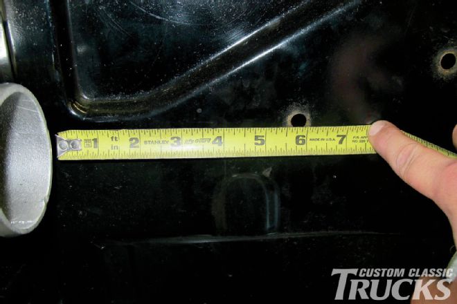
 7. Next, I measured between the mounts to determine the width of the lower bolt hole mounts.
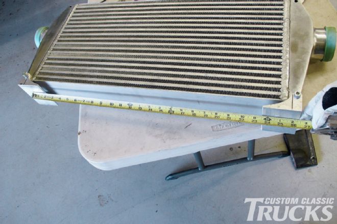
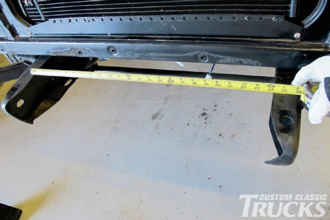 8. Then, I compared that measurement with the chassis to see where we stood. It looks like a distance of about 25½ inches is about right.
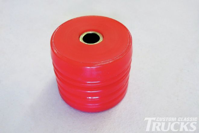 9. To support the intercooler mounts, I’m using a pair of universal mounts from Energy Suspension (part number 9.4102).
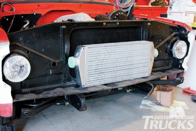
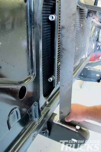
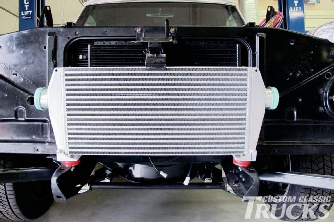 10. With the mounting holes drilled and the universal mounts in place, I was able to mount the intercooler to see where we stood as far as fitment was concerned.
 11. One thing that stood out was the fact that the front framehorns were tilted slightly, which was much more pronounced once the intercooler was mounted.
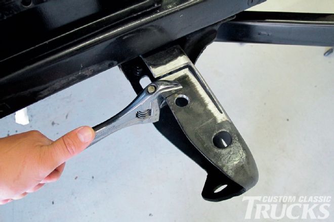 12. To solve this dilemma and bring the unit nice and tight to the core support, I decided to flatten the tops of the framehorns using two cuts from a die grinder. A little coercion from a hammer and an adjustable wrench was all it took to get the proper mounting angle…
 13. …which I checked periodically against a carpenter’s square.
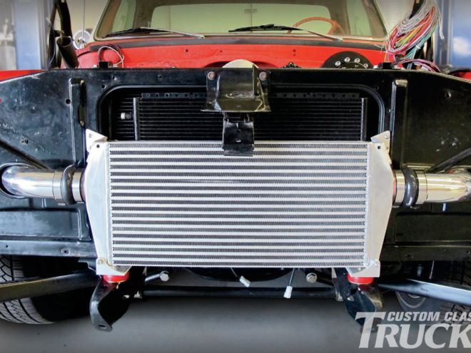
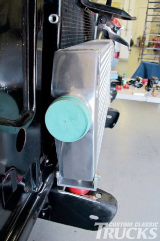 14. The intercooler was then mounted for a final time to check fitment yet again. Note the hood latch mechanism, which I’ve already trimmed to fit around the top of the intercooler.
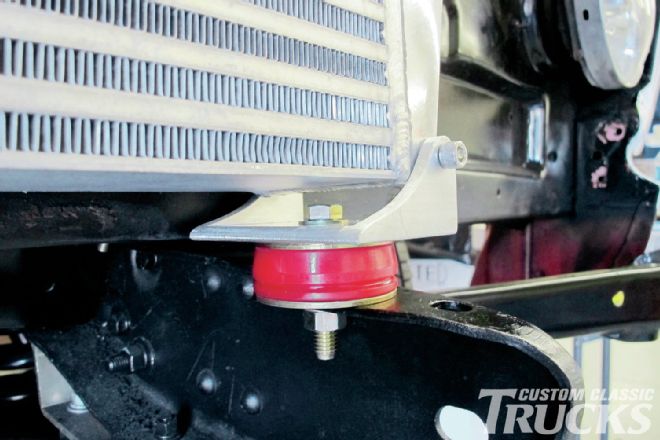 15. The Durometer bushings under the intercooler mounts may not be necessary, but I thought it cheap insurance in the hopes that it saves the intercooler from any harsh vibrations that direct-mounting may have caused.
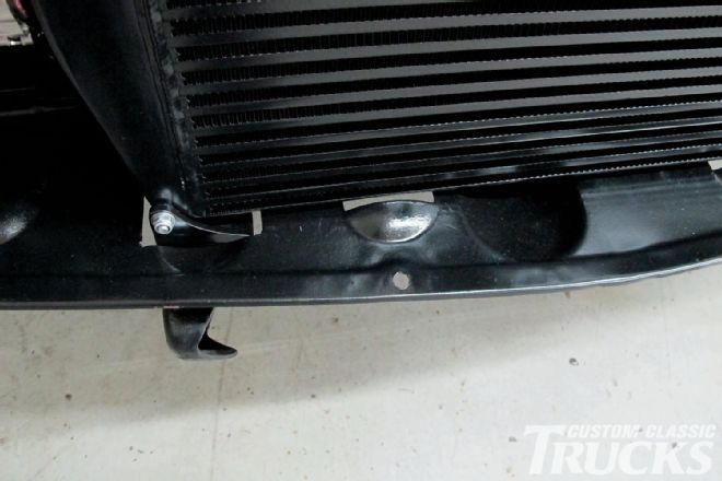
 16. Additionally, since my next step was to add a pair of brackets that will mount the intercooler directly to the core support, I wanted to ensure that I didn’t effectively tie the core support to the frame via the intercooler (since the core support mounts in a similar fashion to the frame). This will allow the core support and the intercooler to flex atop the chassis similar to the fenders and the body. I made a pair of aluminum brackets using ¼-inch aluminum angle, a hole saw, and a couple ¼-inch button head fasteners. With the brackets attached to the core support, I positioned the intercooler a final time before tack welding the brackets to it.
17. Here’s the intercooler mounted and ready for the next phase of fabrication.
16. Additionally, since my next step was to add a pair of brackets that will mount the intercooler directly to the core support, I wanted to ensure that I didn’t effectively tie the core support to the frame via the intercooler (since the core support mounts in a similar fashion to the frame). This will allow the core support and the intercooler to flex atop the chassis similar to the fenders and the body. I made a pair of aluminum brackets using ¼-inch aluminum angle, a hole saw, and a couple ¼-inch button head fasteners. With the brackets attached to the core support, I positioned the intercooler a final time before tack welding the brackets to it.
17. Here’s the intercooler mounted and ready for the next phase of fabrication.
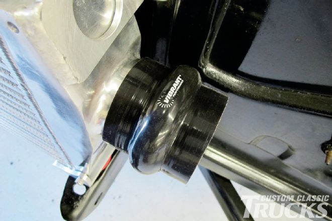 18. You’ve got to start somewhere, so I decided to start at the intercooler, working my way toward the blower and throttle body. First, I placed a Vibrant Performance silicone hump hose on the inlet side of the intercooler.
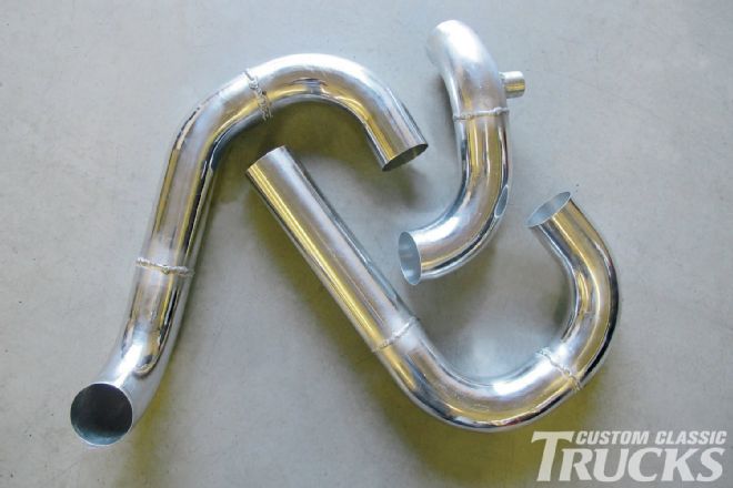
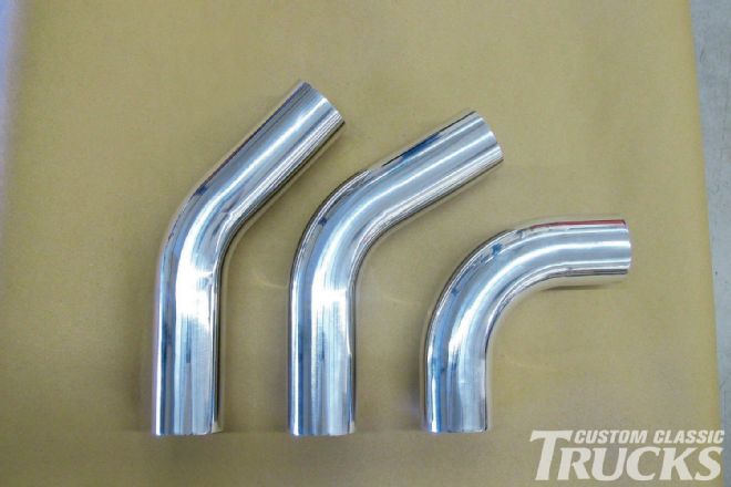 19. Before I ordered up all the bits to do this install, I mapped out how I wanted to run the inlet tract and figured out what angle bends I would need. Luckily, Vibrant offers a nice variety of bends in 3-inch tubing, from 30-180 degrees. Here, we have a 45-, 60-, and 90-degree bend in T6061 polished aluminum, which is how every piece of tubing they sell comes shipped.
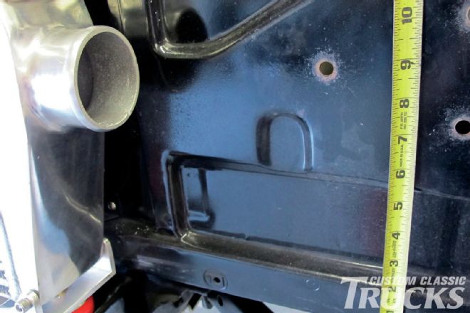
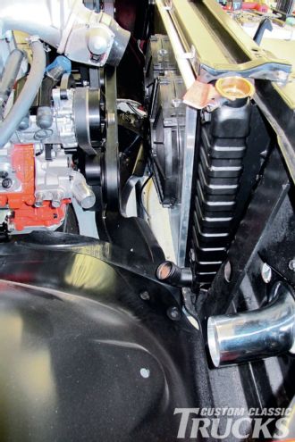
 20. The tubing on either side of the intercooler is going to have to pass through the core support, which will necessitate a rather large, oval hole. I looked for the flattest surface of the core support, compared that measurement from the intercooler with the radius of the 90-degree bend in the tubing I had and picked the spot for the hole.
 21. Though the intercooler assembly will essentially be invisible once the grille is in place, I still wanted to maintain a symmetrical setup at either side of the intercooler. That said, I used the same measurements for the location of the core support hole for each side.
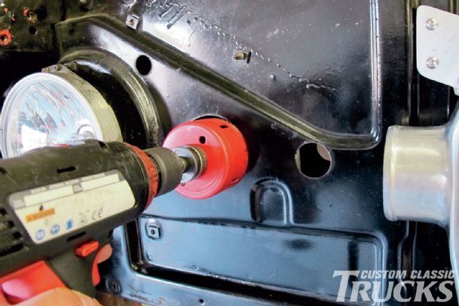 22. With that, I chucked up a 3-inch hole saw in my drill and knocked a hole in either side if the core support.
 23. The resulting hole was large enough for the straight section of 3-inch tubing to pass through, but not large enough to allow the curved portion of the tube to slide back far enough to line up with the inlet on the intercooler.
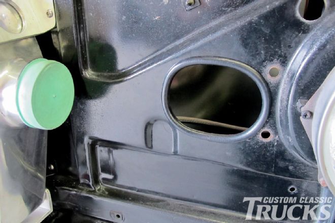 24. A few minutes spent with a tapered burr on the end of a die grinder and I turned that round hole into an oval hole. Silicone ¼-inch vacuum line sliced lengthwise works great for making custom grommets.
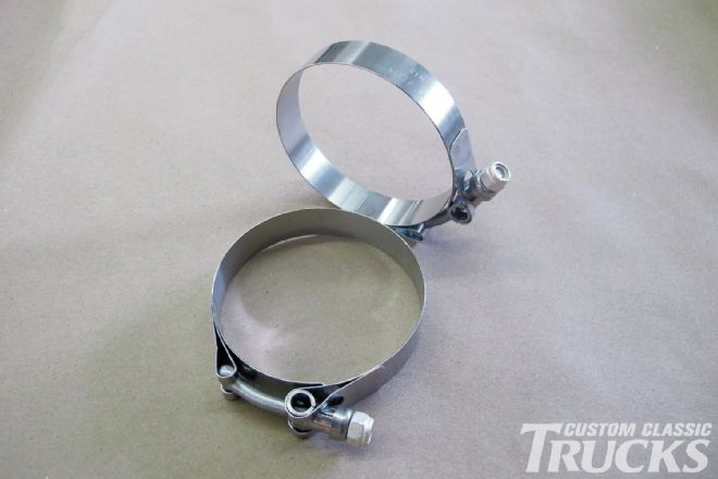 25. I also ordered enough of these stainless steel T-bolt hose clamps to cover every hump hose junction.
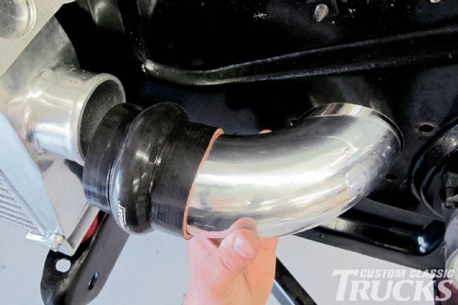
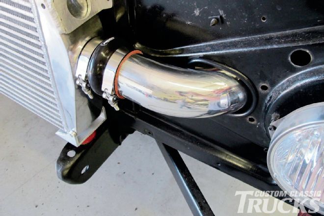 26. Here’s the first bend in place…
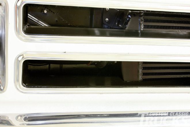
 27. …and the view from behind the core support, so far, so good.
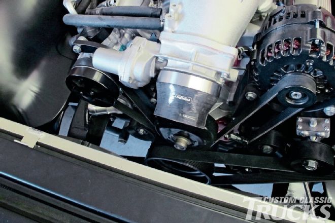
 28. A 90-degree bend will get us out of the supercharger and heading toward the core support. After I measured the length that I needed to trim the stock bend in order to clear the inner fender, I cut it to length on a bandsaw, deburred the cut, then installed the tubing in the hump hose that I attached on the supercharger’s outlet.
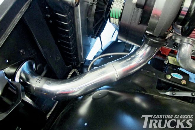 29. Next, I fitted a 45-degree bend to the end of the 90, welded it up, then trimmed it to butt against the existing 90 that mates to the intercooler.
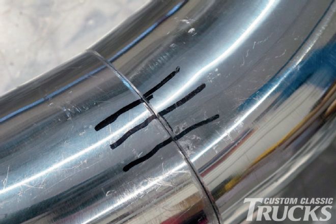 30. Note the three lines that I marked across the seam of the two tubes to be welded. This ensures that their relation remains consistent once everything is removed and set on the welding table.
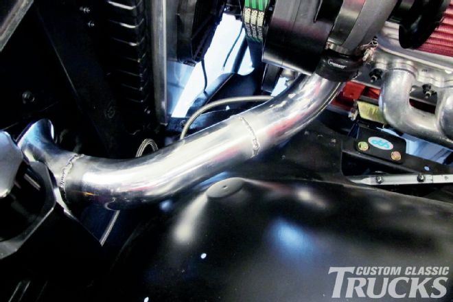 31. With my newly acquired aluminum TIG welding ability being put to the test, I’ve got one side of the intercooler plumbing sorted out.
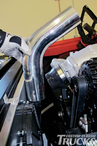
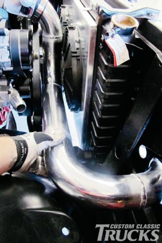
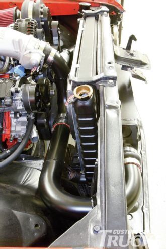
 32. At the opposite side, here’s where the tubing enters the engine compartment from the intercooler. It’s going to make a hard right turn toward the throttle body.
 33. At the throttle body, a silicone reducer is used to adapt the 3-inch tubing to the larger 4-inch throttle body inlet.
 34. A 60-degree bend is going to be used at the throttle body, trimmed to fit between it and the twin SPAL TL fans mounted off the U.S. Radiator fan shroud.
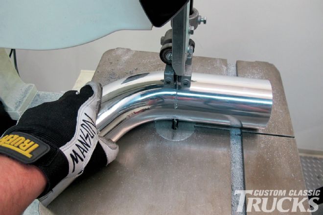 35. A bandsaw makes quick work of cutting the aluminum tubing, especially when it comes to cutting sections of a bend.
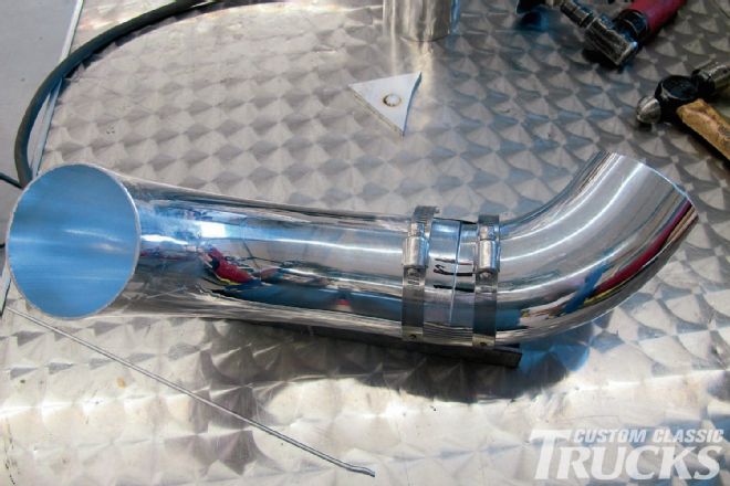 36. To turn the tubing toward the passenger side, a short 90-degree bend will be welded to the existing 60-degree bend that attaches to the throttle body. Here, I’m using the Sharpie marking technique to correctly clock the tubes as well as a pair of hose clamps that are mated with a piece of corrugated tin from a plumbing joint I scored from the local hardware store. This works good to temporarily clamp two pieces of tubing together while they’re tack welded.
 37. Jumping ahead slightly, I’ve welded up another 90 to the intercooler side of things, along with a section of straight tubing. At this point, a decision has to be made whether to weld the entire section together, from the intercooler to the throttle body, or to leave a break in the tubing and install another hump hose. As it turns out, it would be nearly impossible to remove the entire section of tubing as one piece, so we’ll go the hump hose route.
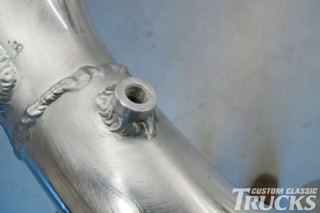 38. To remain flexible, I opted to add a bung to the inlet tract just before the throttle body in case I ever decided to go the water/methanol injection route in the future.
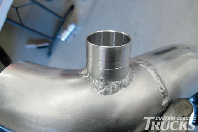 39. TorqStorm also provided me with a blow-off valve that required a bung of its own to be welded somewhere in the inlet tract.
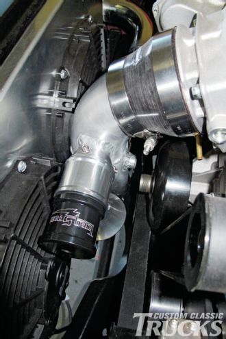 40. I opted to install it up near the throttle body as well. The blow-off valve is adjustable, allowing the user to fine tune when it bleeds off the pressure in the inlet tract.
 41. With the fabrication portion complete, the loose parts were collected and shipped off to Eddie Motorsports to get powdercoated to match the rest of the satin black components under the hood. The one thing I didn’t powdercoat was the intercooler as it’s possible to block the air passages, restricting the airflow that’s allowed to pass between the plates. Instead, I shot it in the same Eastwood Chassis Black that I’ve been using throughout the build.
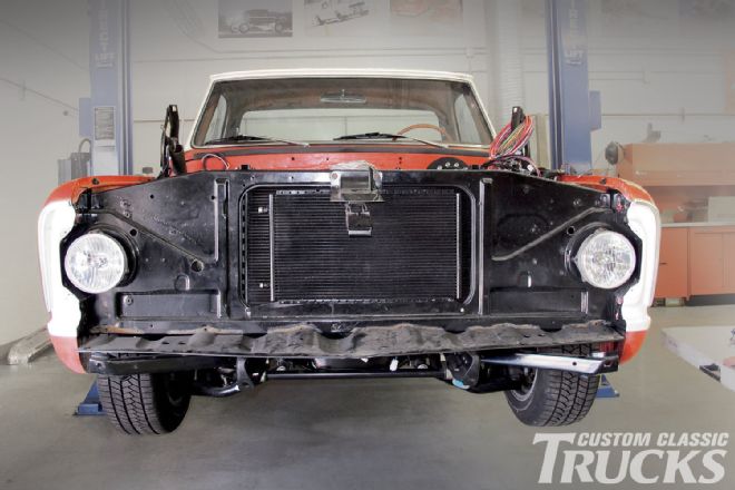
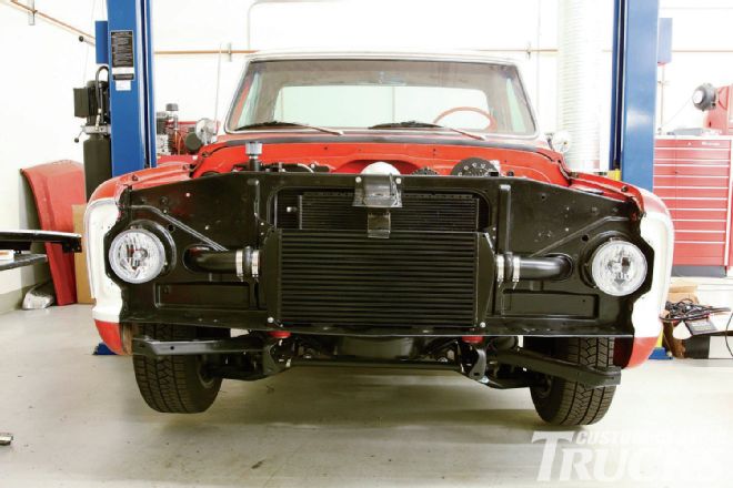
 42. While the tubing was getting coated, I reinstalled the freshly painted intercooler and trimmed the lower valance to clear the new accessory.
 43. One thing that I had to do that we’ll revisit in a future issue, was to delete the grille-mounted turn signals due to them fouling on the inlet tract at either side of the intercooler.
 44. A portion of the lower grille valance also needed to be trimmed in order for everything to fit nice and neat.
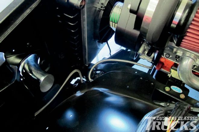
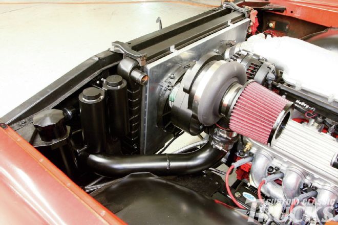 45. A quick walk-around gives a good idea how the inlet tract is run from the supercharger to the intercooler and then on to the throttle body.
 46. It’s interesting to note that the guys at TorqStorm report that dyno results reveal an actual loss in net horsepower when the inlet tract in front of the supercharger makes any drastic bends, like those typically seen in a cold air intake.
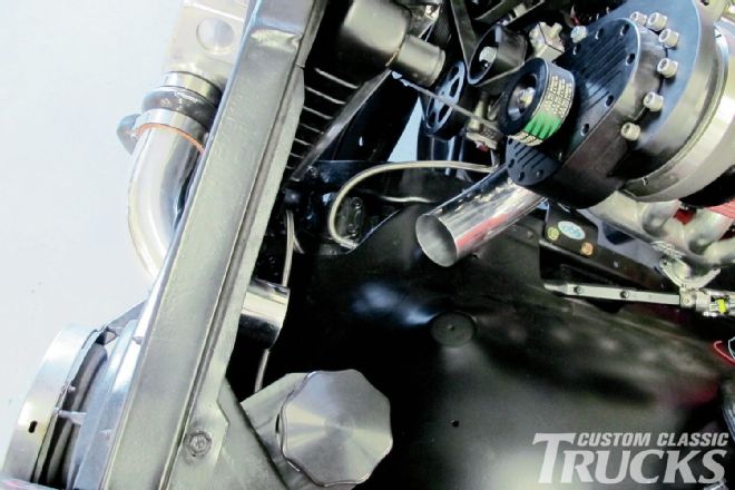
 47. That said, I opted to use a Vibrant Performance air filter mounted directly to the supercharger as the loss in power from ingesting warmer air is actually less than the result from scavenging colder air through a handful of bends.
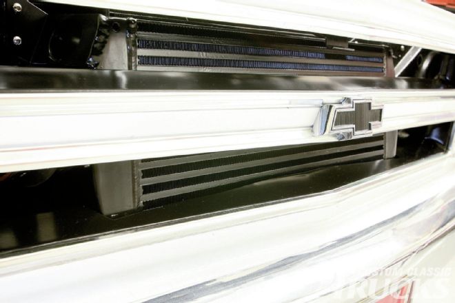
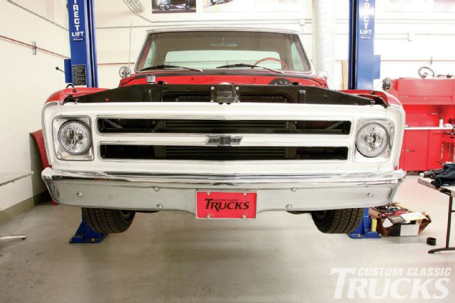 48. With everything blacked out, the façade of our supercharged C10 is pretty unassuming; a nice little sleeper if I do say so myself.