We all have heard the statement that an engine is an air pump; the more air it can pump the higher the output will be. The industry standard for quantifying the amount of air passing through the induction system is a flow bench test. It's commonplace to reference airflow numbers for cylinder heads in conversation and advertisements. The problem is how to decipher this information. If you are like most people, you work under the assumption that more flow is better. But that's not always true. If you ever wanted to understand flow bench testing, read on. And don't forget to check out the next issue for Part II of this story.
Why test for airflow?
One of the theories used to make power in an engine is airflow; so then measuring airflow, in theory, should enable one to establish potential output. The performance industry is focused on maximizing an engine's output on an individual component basis. Then documented gains in airflow should produce predictable results in power production. The question could then be posed, why look at airflow and not power? Whenever designing or modifying components in the induction tract of an engine, the ideal procedure would be to install the part and then dyno check. This would not only be the most accurate, but also the least practical test method. Anyone who has ever ported a cylinder head while quantifying results on a flow bench can only imagine the arduous process of installing the head and running the engine after every port change. Early on it was recognized that a better method needed to be developed, and that was the flow test. A flow bench allows a quick and easy means of quantifying gains or losses to airflow.
On a dyno, air movement into the engine is registered through an airflow meter, installed in a large funnel-like apparatus referred to as a dyno hat. It attaches to the carburetor or throttle body and measures the total airflow into the engine in terms of volumetric efficiency (VE), or the amount of charge fill in the bore. Believing that an engine completely fills the bores on every stroke would be incorrect. The swept volume of the cylinder is filled to the greatest capacity during peak torque production. On most normally aspirated engines a maximum of 85 percent VE is achieved at peak torque. On some very defined race applications, values of 100 percent or slightly above are realized. Forced induction can raise VE to 150 percent or greater. VE levels of over 100 percent on normally aspirated engines are achieved through intake manifold resonance tuning identified as inertia supercharging: the column of air is moving with such energy that it actually fills the cylinders beyond capacity by compressing the molecules and increasing the air density in the bore.In contrast, the flow bench is a series of vacuum motors and registers airflow by measuring it at a constant pressure. Test data derived on a flow bench is measured in cubic feet of air per minute (CFM). Often it may not relate directly to horsepower potential. Flow bench tests do not have the ability to induce inertia supercharging or demonstrate the effects that other components of the engine have on VE. A bi-directional flow bench has the ability to measure air movement in two directions. Intake and exhaust components can be tested.
The flow Test
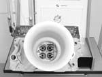
During a test, the subject component is mounted on the flow bench and secured to the test fixture in some manner. There is no prescribed method of attachment. Usually it consists of nothing more than large Vise-Grips or C-clamps along with some type of gasket. When testing a cylinder head, an adapter the same size as the bore is necessary. This maintains the relationship of bore shrouding that the cylinder head will experience on the engine. An opening fixture is used to actuate the valve to specific lift points. Lightweight test springs are installed to keep tension on the valve. When measuring flow on the intake side, more accurate results will be obtained with a radius on the inlet port in lieu of the straight edge of the cylinder head casting. When testing the exhaust port it's necessary to attach a six-inch extension for the same reason. The radiused inlet along with the exhaust extension allows for a smoother transition. Without these fixtures, the air will shear and give readings that are lower than the actual potential of the port. Radiused inlets can be formed with modeling clay while pre-made Plexiglas units to a specified intake manifold gasket size are available. The exhaust extension is customarily a 1.75- to 2-inch piece of straight exhaust pipe.
Of paramount concern is repeatable test procedures when checking a modification. The most common component for flow testing is the cylinder head and that is also a component where many mistakes in the test can be made. Whenever comparing flow data from different benches there will always be a slight variation due to operator error, calibration of the bench, fixturing, electrical current and air temperature. Working with a cylinder head, a large variation in flow numbers can be achieved by using different-sized bore adapters. This is a common mistake since many shops assume that in the case of a small-block Chevy, the bore is 4.030 inches. A cylinder head that is flowed on a larger bore may very well show improved flow numbers from the additional unshrouding.
A flow bench test is done at a fixed test pressure. Due to this, the test value will need to be identified. Higher test pressures yield higher flow numbers. SuperFlow Corporation, the industry standard for flow benches, suggests 25 inches of water. The test pressure is read on a manometer attached to the bench while a rotary valve is controlled by the operator to arrive at this value. The aftermarket performance industry commonly flows at 28 inches of water, yielding higher flow numbers from the same port. A port that flows 200 cfm at 25 inches of water will now flow 212 cfm at 28 inches. Shops that have smaller or older flow equipment may not have the capacity in cfm to move a sufficient air volume to create higher test pressures. This style of equipment is usually operated at 10 inches of water. The results can be converted to any value with the chart provided in this text.
When discussing flow numbers for a potential porting job or the purchase of a set of heads, always identify the bore size used along with the test pressure, or you may not get what you paid for.
Before starting the procedure a leak test needs to be performed. This is done with both valves closed. There should be no leakage. If leakage is present in any area it should be corrected or the amount of leakage needs to be subtracted from the test data. To get the most benefit from flow testing it needs to be realized that either valve spends more time traversing the lift range than dwelling at maximum lift. Herein lies the fallacy of most published flow numbers, i.e., that they are at maximum lift and may also be at lift values higher than your cam will generate. A port is considered stalled when increased valve lift yields little or no increase in air volume, or an actual decrease. Low valve lift flow is critical for power production and a head that has better low lift numbers in most cases will outperform one with superior high-lift results. The recommended procedure is to calculate the test heights with an equation that takes the valve diameter and then multiplies it by a factor to determine seven test points.
The equation is: Net Valve Area =0.785 (valve diameter2-stem diameter2).
Once this is derived, it's multiplied by the Lift/Diameter (L/D) equation of .05, .10, .15, .20, .25, .30, .35, to determine the specified lift points for testing. This is done to make an accurate comparison of flow for different valve sizes in the same head. It is an acceptable practice for an experienced operator to flow at .050-inch lift graduations and not do the (L/D) calculations. L/D calculations are necessary when comparing the flow results of different size valves since they can be further broken down into valve efficiency, which represents cfm/square inch of valve area.
Whenever working with a flow bench to quantify changes to a port as it is being modified, it is essential to make your procedure as repeatable as possible. Dowel-pinned adapters are recommended for repeatability in positioning the cylinder head. Accurate valve opening fixtures that are rigid to avoid defection will ensure that the test data is accurate. Inaccurate flow data is worse than no data at all.
Ancillary tools that are used with the flow bench are velocity probes and threaded wands and steel balls on a welding rod. A velocity probe is used to measure the speed of the intake or exhaust port flow while the head is being tested. Using an additional manometer that's attached to the bench, velocity in feet/second can be derived. If the air is traveling too fast around the short-turn radius, it will shear or skid, reducing the effective valve area and choking flow. In most intake port designs, a threshold of 350 feet/second is the maximum speed for the air to follow the contour of the port. It must be remembered that when checking velocity on intake ports, the dynamics of inertia supercharging cannot be duplicated. Subsequently, exhaust port velocities do not calculate the thermal expansion and contraction from heating and cooling that occurs during blow-down and the pumping loop.
Threaded wand probes can be inserted in the port to visually display the movement of the air. Steel balls attached to welding rods are used along with clay to change the configuration of the port easily and temporarily to determine the effect on flow. Additional information can be quantified with the use of a swirl or tumble meter. In-cylinder charge motion can be documented with this equipment when attached under the bore adapter. Charge motion needs to be evaluated when developing a port since it has an effect on combustion.Recording the test results is just as important as performing an accurate test. Each operator has his or her own method of data recording. It varies from lift points and flow values handwritten on a piece of paper to advanced computerized data recording with Audie Technology Flow Pro software. All too often, a flow bench operator does not recognize the value in port mapping, valve area efficiency and graphing the port's performance. The Flow Pro software not only allows the operator to view all of this data and graphs easily, it becomes a learning tool for the head porter.
Stay tuned for the next issue, where we will delve deeper into this fascinating subject.
PHOTOS AND GRAPHS COURTESY OF THE MANUFACTURER