Whether it’s a ground-up, refurbish, or a search and repair mission on your latest project, tracking down electrical problems don’t have to be an unsolvable mystery. We found ourselves having some minor, albeit annoying, electrical woes with our ’62 Chevy and thought before getting too deep into any upgrades we’d start by diagnosing the electrical system.
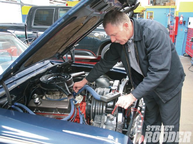
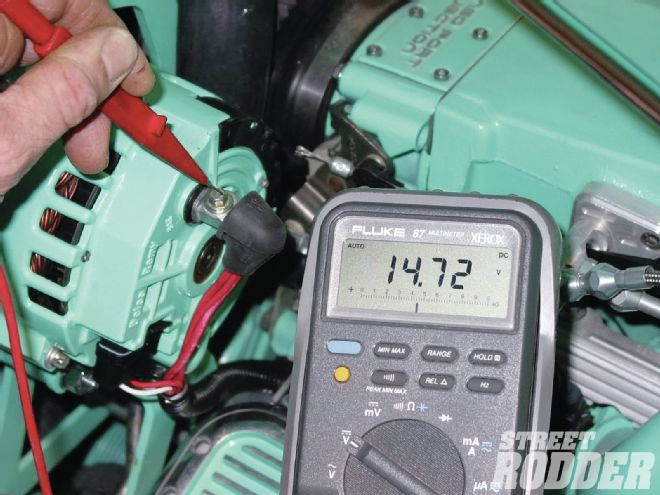
With the engine running, check the output at the back of the alternator and see if it’s the same as what the voltmeter in the car is reading. If it’s higher, the problem is excessive load on the fuse center, wiring, or ignition switch (most ignition switches have a maximum capacity of 60 amps). If the output is the same, the belt driving the alternator may be slipping or the alternator may have an internal problem. Once again we are looking for voltage between 13.6 and 14.8.
Our ’62 was converted from a generator to a 60-amp alternator somewhere in its life. From the time we bought the car it would display slow cranking characteristics. After we installed electric fans the slow cranking problem persisted, even worse. You know the sound and the feeling; “Oh no it’s not going to start.” We figured a bad battery was too obvious, but that’s where we started. It’s surprising how many times the problem isn’t the battery but another link in the electrical system. That’s not to say a battery can’t go bad but often it gives up the ghost because other electrical system woes inflict abuse on the battery.
Since nothing in the electrical system can tell you “how they are feeling” you need to get out the equipment and give the system a once over. There are simple and sophisticated pieces of test equipment available for any hot rodder to use and oftentimes solve your own problems. If not, you can take the route of a professional mechanic who is qualified to analyze electrical systems. It will also be helpful if you can provide as much data as possible, such as one of the taillights isn’t shining brightly, the ground strap is missing from the engine to the chassis, etc. This additional data is very helpful in finding the faulty component and the root cause. Remember you need to fix both the cause and the faulty component.
In checking our Chevy we found that while our battery and alternator were in good condition they weren’t the capacity that was now required. As is often the case accessories were installed, such as stereo and electrical fans, without any consideration for the additional electrical load.
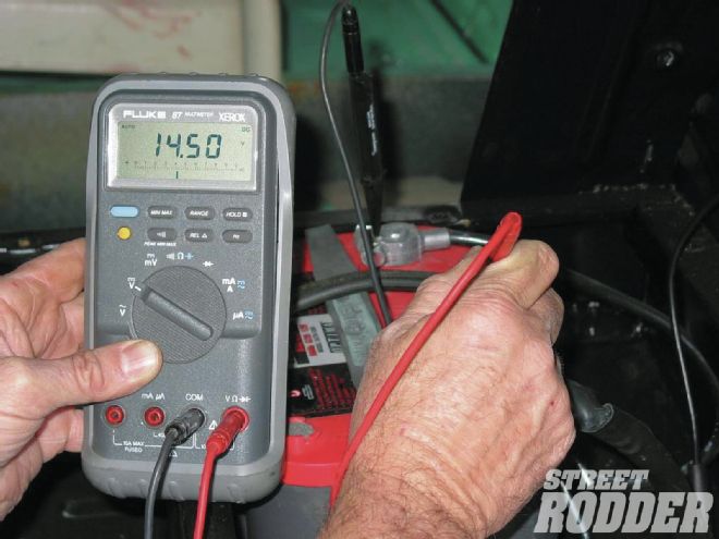 Next, check the voltage at the battery; it should be the same as the alternator output. If it is lower by more than 1/2 V, there’s resistance or a bad connection between the two. Here it’s shown that the voltage drop is about 0.2V drop, which is OK. With the new 100-amp plus alternators, an additional wire, 10 gauge or larger, between the alternator and the battery source (starter solenoid) is recommended. If turning off a specific item allows the voltmeter to return to its normal reading then that item is in need of a relay to allow current to be supplied directly from the battery source.
To begin our project we visited Rudy Renka of Rudy’s Garage (Costa Mesa, CA) whose shop is near the magazine. He has helped us for years with our stockers and from time to time we bring in our hot rod projects. A longtime drag racer, he gets what we are doing and how it should be done.
After he tested our Chevy he found that our 600 CCA battery needed to be replaced with an 800 CCA battery, so in went a new Optima and a fresh battery tray from Trans-Dapt. He also found the alternator charge line that ran to the battery wasn’t a large enough gauge wire; it needed to be a 10-gauge wire wrapped in Trans-Dapt flexible wire harness tubing for protection. We took out a voltmeter and determined that the improper gauge wire resulted in a voltage drop. We were experiencing a voltage drop (1.4 V on the positive side of the battery and a 0.25V drop on the negative side of the battery). Ideally it should have shown a draw of 0 V. During the cranking process the old charging system would show a voltage drop of 0.75 V on the positive side of the battery and a 0.8 V on the negative side. The battery also produced 175 amps on cold cranking and 190 amps on hot cranking.
To finalize our solution Renka recommended we go to new heavy-duty battery cables, which we rounded up from Painless Wiring, and a battery to body ground wire. Proper ground is imperative for an electrical system to function properly. A commonly forgotten ground is the one that runs from the negative battery terminal to the body. Typically you can achieve this ground by going directly from the negative lug to the upper radiator core support. Take a look on many a new car and the odds are you will see a small wire coming off the negative terminal that’s already attached to the heavy-duty battery cable. The other end is attached to the body ground. The battery needs to be ground strap to the body, then to the engine, and then the engine to the chassis. Another typical ground will go from the valve cover to a spot on the firewall.
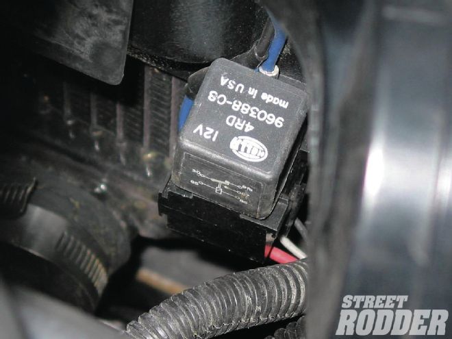 Relays should be placed close and in a direct line to the power source load to prevent any voltage drop. A side benefit is that motors and solenoids will last longer and be more efficient when ample voltage is supplied to them. This relay is mounted on the radiator core support for the electric fan.
Test Equipment
Voltmeters are today’s way of seeing what the vehicle’s electrical demands are doing and how these demands are being met. They can tell us many things, from how the charging system is functioning to if the loads on the wiring are too great. Knowing how to read the voltmeter is the key.
This is something that you can do at home with a few specialty tools or take to a trusted mechanic and he can give you an overview. For instance, the Auto Meter DM-40 or DM-46 Digital Volt/Ohm/Ammeter is an excellent toolbox addition for the hot rodder who likes to get into electrical systems.
Battery Cables
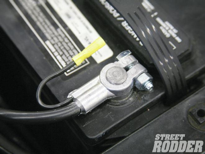 The negative battery cable often (especially Detroit iron) has a secondary wire that’s there to allow a splice for an additional battery ground to the sheetmetal; such as the radiator core support.
Battery cables are an important part of any car, hot rod, or otherwise. Except with our hot rods, when it comes to cable lengths oftentimes we need custom length cables in order to have both a good looking and well functioning pair of cables.
Painless Performance has battery cable kits to solve these problems. The PN40100 kit has a 15-foot red positive cable and 3 feet of black negative cable for those applications where the battery is under the hood, close to the engine. The PN40105 kit is for those applications where the battery is located in the trunk or away from the engine and includes a 16-foot red and 16-foot black cable. All cables are No. 1 gauge.
All Painless battery cable kits include 3/8-inch ring crimp-style copper terminals, color-coded heat shrink with glue and side-post battery adapters. The heat shrink with glue prevents moisture from entering into the cable and causing corrosion.
With a few minutes and a hammer-driven crimper, you can have professional-built cables that will carry the current needed to start your small or large engine.
Relays
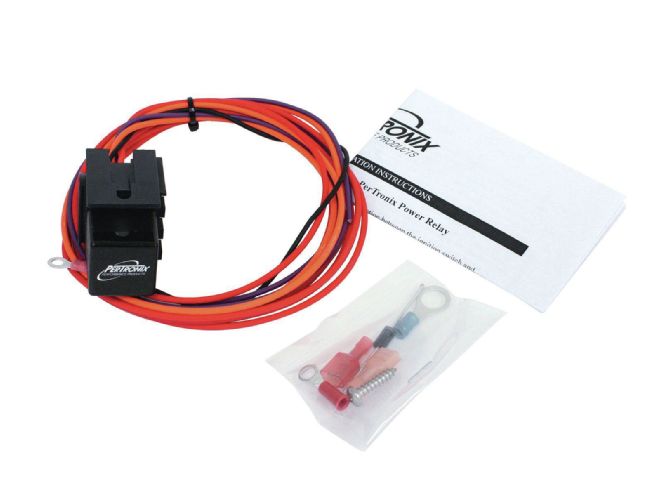 The PerTronix Power Relay Kit (PN 2001) works with most AMC, Chrysler, Ford, and pre-’74 GM vehicles and are equipped with OE resistor ignition feed wires. PerTronix Ignitor II and III ignition systems require a full 12V power connection between the ignition switch and the positive coil terminal, which requires bypassing the ballast resistor or resistor wire, and in many cases, the original resistor wire is buried in the vehicle’s wiring harness.
Relays are today’s answer to the power transfer of current to those hungry creature comforts. Relays are a lot like voltmeters. Proper use will provide relief of worry about what’s happening in your electrical system.
Proper installation of relays is just as important. Relays require protection from overloads, as any circuit does, which is commonly done with automatic reset circuit breakers or maxi-fuses. Relays need to be placed in as close to a direct line from the power source to the load as possible to prevent any voltage drop. A side benefit is that motors and solenoids will last longer and be more efficient when ample voltage is supplied to them.
Since a relay only requires about as much current as a dash light to activate, the load on the switch and its wiring is almost eliminated. The contacts inside the relay are designed to carry high amounts of current and are connected by heavy wires between the power source and the load.
Fan Relays
We have all heard the stories about burning up electrical systems, cars overheating in traffic, and air conditioning systems failing due to the fact that the electric fan didn’t come on or didn’t have enough current so it could run at maximum speed. All kinds of problems can occur when the fan can’t produce the airflow desired in today’s cars and trucks; the myth of “a bigger alternator will fix it.” Nothing makes a fan produce airflow like old-fashioned current.
Proper current flow must consist of two things, voltage and amperage. Voltage may be compared to horsepower and current could be compared to torque. Voltage will help the fan run faster but it takes current to get it started. These two things depend greatly on one another and will always offset each other. When voltage goes down amperage will increase and when voltage goes up the fan will require less amperage.
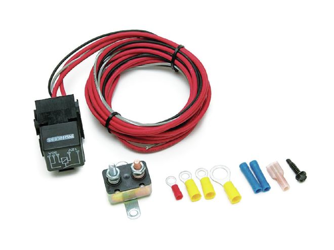 Most aftermarket engine control systems have a grounding wire or connection to operate an electric fan relay. These computers are normally programmed to a specific temperature for the computer to allow a ground trigger for the relay. A relay kit like the Painless (PN 30109) PCM Fan Relay Kit is designed to be triggered by the PCM (ECM) and allow current flow directly from the battery source to the fan.
Many things can contribute to voltage and amperage loss in an electrical system. The most common is the wiring is too small for the circuit or the current is routed through the circuit through too many devices or switches. In any high-amperage draw circuit, a relay should be used to help eliminate current drop. As the old saying goes ”the shortest distance between two points is a straight line,” which holds true with electricity. A relay mounted between the battery source and the fan will almost eliminate all current loss. No more ignition switch overheating and voltmeter fluctuations.
In most aftermarket engine control systems today we have a grounding wire or connection to operate an electric fan relay. These computers are normally programmed to a specific temperature for the computer to allow a ground trigger for the relay. A relay kit like the Painless 30109 PCM Fan Relay Kit is designed to be triggered by the PCM (ECM) and allow current flow directly from the battery source to the fan.
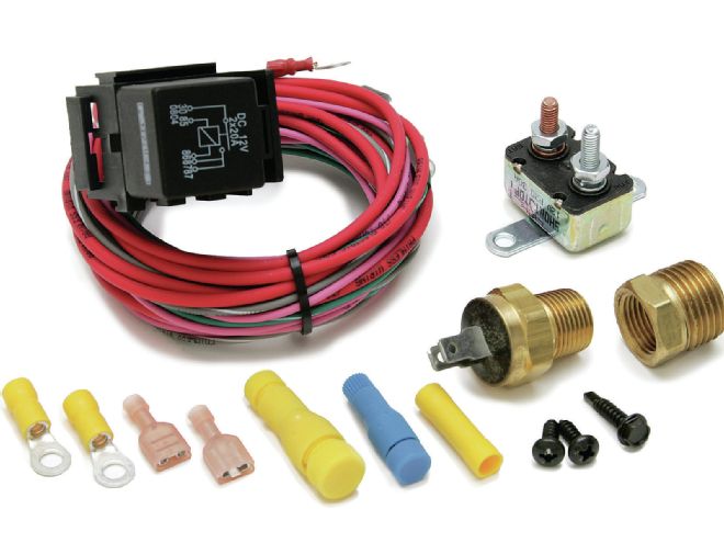
Air conditioning also plays a big part in the cooling of the engine and the cooling of the cabin. The fan needs to run when the engine is at operating temperature as well as when the A/C compressor is in operation. These two instances may not be at the same time. Painless Performance has developed a fan relay that will allow the fan to operate at a preset engine temperature as well as when the A/C compressor is turned on. This design will allow maximum cooling efficiency of the engine and A/C system.
The new Painless relay PN30114 (200/180 degree thermostat) and 30115 (185/170 degree thermostat) are easily installed and come with circuit protection, wiring, terminals, a thermostat, and easy-to-follow instructions.
12 Ways to Screw Up (or Not) Your Wiring Harness
 The Painless relay (PN 30114, 200/180 degree thermostat; and PN 30115, 185/170 degree thermostat) comes with circuit protection, wiring, terminals, a thermostat, and easy-to-follow instructions.
We asked Dennis Overholser of Painless Wiring for some tips on how not to treat your wiring system. He said he didn’t have to look too far as the following examples he tells us happen far too frequently and can lead to disastrous results.
If you have a harness more than a couple of years old and are just now installing it in your ride, be safe and contact the manufacturer to be sure it has the upgrades needed to comply with your needs.
1. The proper way to strip and crimp terminals
Do not strip away too much insulation thereby leaving copper showing.
2. Using circuits designed for relays without the relay
Make sure ignition switch wires do not become severely burnt due to the electric fan and air conditioning power drawn directly through the switch rather than through a relay. A bank of relays will control all the high load circuits in the car. They prevent overloading the switches as well as the fuse block.
3. Installing a system smaller than the vehicle’s needs
Be careful not to add too many extra circuits on after the system is installed. This can cause excessive current draw through the fuse block and a possible major meltdown of the fuse block.
4. Improper grounds
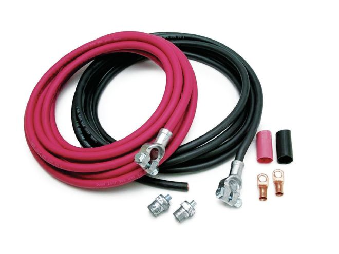 The Painless battery cables come with side post adapters, copper ring terminals, and heat shrink with glue inside to help prevent moisture from causing corrosion in the cables.
Ground straps are very important yet many rodders make the common mistake of not reattaching a ground strap and servicing the engine. A proper ground cable from the engine to the frame is critical as is a ground cable connecting the frame to the body or a body support in the case of a fiberglass car. Junction blocks are another neat way to make sure the dash and accessories will be properly grounded.
5. Lack of proper wire supports and routing
A little time doing proper routing will make the underdash area neat and easily serviced. Insulated wire clips are a safe way to keep wires in their place.
6. Improper overall circuit protection
Wiring the alternator and fuse block input wires directly to the battery source is a disaster looking for a place to happen. A maxi fuse or a fusible link can be your savior if a major electrical malfunction occurs.
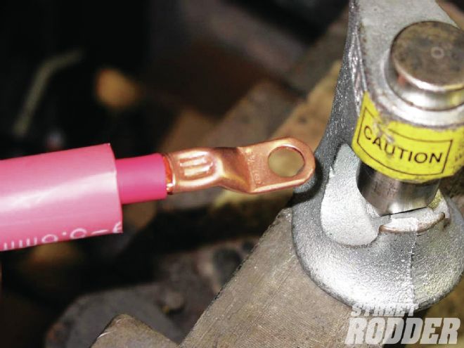 A standard heat gun will be sufficient to make the shrink tight around the cable and terminal. Glue will ooze out slightly to show the water-tight fit.
7. Cutting the wires too short during installation
Make sure to cut wires with a “little extra” so that they aren’t pulled too tightly. Pulling a little extra wire before cutting will make installation a lot easier and safer.
8. Routing wires around hinges and areas that move
Wiring for accessories like power windows, power locks, trunk lights, and underhood lights should be attached securely and wrapped in some type of covering to protect the wires from possible chafing. Aftermarket tubes and boots are ideal.
9. Routing wires through sheetmetal
When routing wires through an inner fender, firewall, or any sheetmetal, always use a grommet or other form of protection. The sharp edge of the metal will soon destroy the wire insulation and cause a short to ground.
10. Using wires designed for low-amperage on high-amperage circuits
 Permatex Dielectric Grease will protect electrical connections and wiring from salt, dirt, and corrosion. Ideal for use with battery terminals, spark plug boots (prevents spark plugs from fusing to boots), electrical connections, and prevents voltage leakage around any electrical connection.
Eighteen-gauge wire is designed to trigger a cooling fan relay. Using this wire to power the fan directly will cause the wire to get hot and will prevent the fan from running efficiently.
11. Substituting incorrect fuses
If you have a problem in a circuit, how many times have you heard the story, or done it yourself, by inserting a piece of foil to keep the lights or something else on? It’s only a matter of time until something starts burning.
12. Not reading the instructions
Contrary to popular hot rod wisdom, instruction manuals are a wealth of information and are meant to be read and absorbed. To prevent the possibility of routing wires to the wrong destination, not using a relay in a specified circuit or a host of many things can be avoided by simply doing the proper research ahead of time.
Charging an Absorbed Glass Mat Battery
In the world of hot rodding absorbed glass mat (AGM) batteries have become common place. The following Optima Batteries tech tips will keep any lead acid battery performing at its best. These are all important factors to consider when maintaining any absorbent glass mat battery.
 Permatex liquid electrical tape keeps electrical connections together and insulated. It creates a flexible, vinyl polymer seal that’s both waterproof and durable. It creates a flexible, vinyl polymer seal that’s both waterproof and durable.
Alternators are not chargers: Do not rely on the vehicle alternator to do the work of a charger. An alternator is meant to maintain a vehicle battery, not charge it.
Newer chargers incorporate newer battery technology: Many newer battery chargers, or Smart Chargers, have microprocessors that collect information from the battery and adjust the current and voltage accordingly. Some have different settings for charging traditional wet cell (flooded), gel, and AGM batteries.
Sulfation limits battery performance: All lead acid batteries can experience sulfation, the formation of lead sulfate crystals upon discharge. Look for a charger with a de-sulfation mode to help condition the battery and keep it performing at its best.
All batteries eventually die: Batteries are a consumable product, meaning no battery will last forever. The goal is to consistently maintain your battery to get the highest performance and most life out of it.
Charging Considerations for AGM Batteries
 Permatex Battery Cleaner and Battery Protector & Sealer are ideal for prepping battery terminals and cable ends. These products when used properly will go a long way toward preventing corrosion and guaranteeing a free flow of electricity through the cables.
Different chargers have different capabilities: Although under normal conditions most 12V automatic battery chargers will work on an AGM battery, the battery will only charge to about 80 percent of its full capacity. Many newer battery chargers have settings specifically for AGM batteries and some even have separate settings for Optima RedTop and YellowTop batteries.
AGM and gel technology differ: Remember the technology of an AGM battery is not the same as a gel battery, which has its own charging requirements. If the charger offers different modes, select the correct one for your battery. Using the gel setting to charge an AGM battery will not fully charge and over time will actually damage your AGM battery.
Lower is better: A low amp charger (1-10 amps) is always the best choice for charging any lead acid battery. It is faster to charge at higher amperage, but it generates a lot of heat, which reduces the life of a battery.
Charging an AGM at 10.5 V or greater: No problem, under normal starting conditions, an Optima battery should never experience “at rest” voltages below 12 V. Most 12V chargers and alternators have no problem recharging an Optima if it has an “at rest” voltage of 10.5 V or greater.
 The Xuron Model 505 Adjustable Wire Stripper/Cutter easily accommodates different wire gauge sizes and locks in the closed position to fit into a pocket, pouch, or tool kit when not in use. Featuring a thumb-adjustable cam, stamped with 12 to 26 AWG (2.05 to 0.405 mm) gauge sizes, this time-saving combination tool is designed for stripping and cutting solid wire.
How to Resuscitate a Deeply Discharged AGM Battery
One of the benefits of AGM is having incredibly low internal resistance. The internal resistance, to a large extent, determines the battery performance and runtime. The lower the resistance, the less restriction the battery encounters in delivering necessary cranking power. Lower resistance also enables the battery to accept a charge more quickly.
Today, most battery chargers have built-in safety features. A charger that immediately recognizes a defective battery may not attempt to charge it for safety reasons. A traditional battery that has 10.5 V or less is typically considered defective, which could be from a short, a bad cell, or other defect. However, in most cases, a discharged AGM battery has simply slipped below the minimum voltage threshold of the charger and can easily be recovered. Absorbent glass mat battery failures are commonly caused by use in improper applications. If either occurs, Optima recommends the following three options for bringing a capable AGM battery back to life:
Recovery Option 1: The Best Solution, AGM-Specific Chargers
The best method for recharging a deeply discharged AGM battery is to purchase a modern charger incorporating the latest battery technology. Many chargers now have AGM-specific settings and desulfation steps that help recondition and recover deeply over-discharged AGM batteries.
Recovery Option 2: The Do-It-Yourself Solution
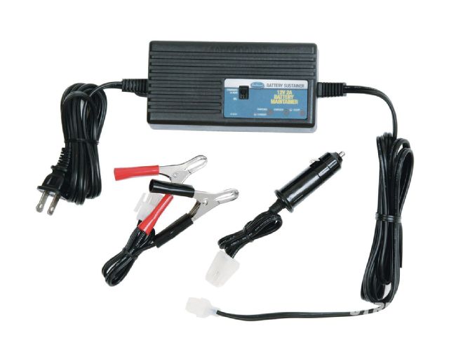 The Eastwood Battery Sustainer (pictured) comes in two versions (PN 13537) and a Battery Sustainer Plus with built-in battery charger (PN 13538). Battery Sustainer is ideal for hot rods that are driven infrequently but need to have their battery maintained and ready to go on a moment’s notice.
This DIY recovery method using the equipment you may have in the garage requires a battery charger, jumper cables, a good battery (preferably above 12.2 V) and the drained AGM battery. This step-by-step method will allow the deeply discharged battery to be charged:
1. First, hook up the good battery and deeply overdischarged AGM battery in parallel—positive to positive, and negative to negative. Do not have the charger connected to the battery or turned on at this stage.
2. Second, hook up the “good” battery to the charger cables. Turn on the charger. The charger will recognize the voltage of the good battery and start providing a charge.
3. After the batteries have been hooked up for about an hour, check to see if the AGM battery is slightly warm or hot to the touch. Batteries naturally become warm during charging, but excessive heat may be an indication there is something seriously wrong with the battery. Also beware of a hissing sound coming from the safety valves. If either occurs, immediately discontinue the charging process and refer to Recovery Option 3.
4. Check back every hour to see if the AGM battery has returned to 10.5 V or above. If it has, disconnect the charger from the wall outlet and remove the good battery from the charger. Now, connect only the deeply drained AGM battery to the charger. Turn on the charger and continue until the AGM battery returns to full capacity, or until the automatic charger completes the charging process. In most cases, the AGM battery will be recovered.
Recovery Option 3: Enlist the Professionals
If you do not own a battery charger and do not want to make the investment, this is the option for you. Take the battery to a professional battery specialist who is knowledgeable about AGM technology.
Guideline to what circuit/ what amperage fuse