 A simple voltmeter and some basic electrical circuit knowledge can go a long way toward eliminating those nagging electrical problems.
Electrical snafus are among the most annoying problems with older cars. Unlike tires or bodywork, there's something about electrical systems that seems to baffle many car crafters. We could blame it on 12-volt voodoo or the curse of mummy wiring, but the best way to get past all those superstitions is with some good old-fashioned electrical knowledge. Most direct-current conundrums can be solved with basic diagnostic work that will point to a simple repair. Dig out that test light and multimeter because we'll use them as the tip of our wiring attack spear to root out all those nasty electrical gremlins.
Voltage Drop Testing
Many common electrical difficulties can be diagnosed by using a simple voltage drop test to discover the root of the problem. The voltage drop test is a dynamic test intended for use mainly with high-current draw systems, such as the starting system, charging system, or items such as a heater fan, electric fuel pump, or electric cooling fans. Performing this test will require a digital multimeter. The number displayed on the multimeter during the test will indicate the amount of voltage lost to resistance through a connection or a cable in the circuit. The beauty of this test is that we can break down a complex circuit into individual components to home in on the real problem.
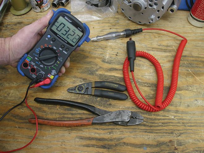 The one electrical diagnostic tool that any good car crafter should have is a handheld multimeter from Actron or this Equus meter. They can measure voltage, ohms resistance, DC current, as well as rpm, dwell, and other goodies. This model 3340 Equus retails for $96.99, but basic units go for $25. Other essential tools include wire strippers, crimp pliers, and a quality test light.
A voltage drop test uses small voltage readings measured within a circuit as an indication of resistance. Most high-current flow, low-resistance circuits-like a simple length of battery cable-should generate a 0.10- to 0.20-volt drop during a dynamic test. Dynamic testing means this voltage drop can only be measured when a load is applied to the circuit, as when the engine is cranking.
If the cable measures 0.75 volt, for example, this would represent excessive circuit resistance. Making the connections for the test is easy. You set the meter on volts and place the negative lead to one end of the cable and the positive lead to the other end of the battery cable.
Not too long ago, we ran into a hard-start issue with a '68 small-block Camaro. The car had a new battery, cables, and starter but still suffered slow-cranking woes. The new cables were suspicious, so we checked the voltage drop for the battery cables by setting our multi-meter on the lowest scale (some models, like our Equus, do this automatically). Next, we pulled the coil wire out of the distributor cap and grounded it so the engine would not start. We placed the multimeter test leads on the positive battery post end of the positive cable and the other lead on the positive cable connection at the starter motor. Then we had a friend crank the engine while we read the meter. We discovered that brand-new discount-store battery cable measured a 0.91-volt drop (roughly four times the normal voltage drop), which means it had a tremendous amount of resistance. On the ground side, the voltage drop (resistance) was even greater at a 1.1-volt drop, adding even more resistance to the circuit. We swapped both cables for high-quality, 1/0 multistrand welding cable, available through either MAD Enterprises or Painless. Retesting resulted in only a 0.20-volt drop in each cable. The car cranked over like it had 24 volts because the battery could now deliver all its cranking amps to the starter instead of losing it to resistance.
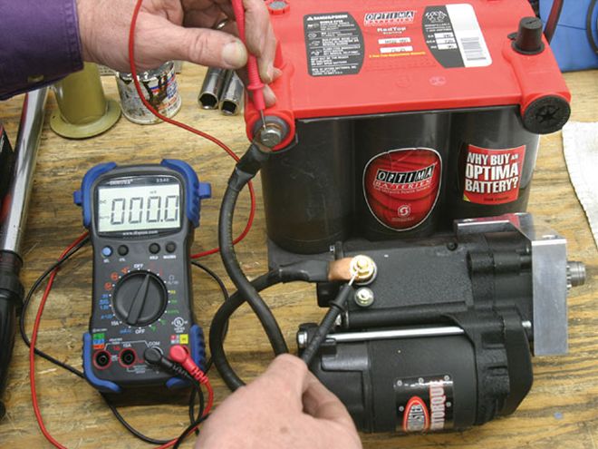
This photo simulates a voltage-drop test on the positive battery cable. Place the positive voltmeter test lead on the battery side of the cable and the negative lead on the starter motor cable connection. If the voltmeter reads more than 0.4 volt, there is excessive resistance in the cable. Remember, voltage drop will only work with the engine cranking. Do not crank the starter for more than 10 seconds to avoid overheating and damaging the starter.
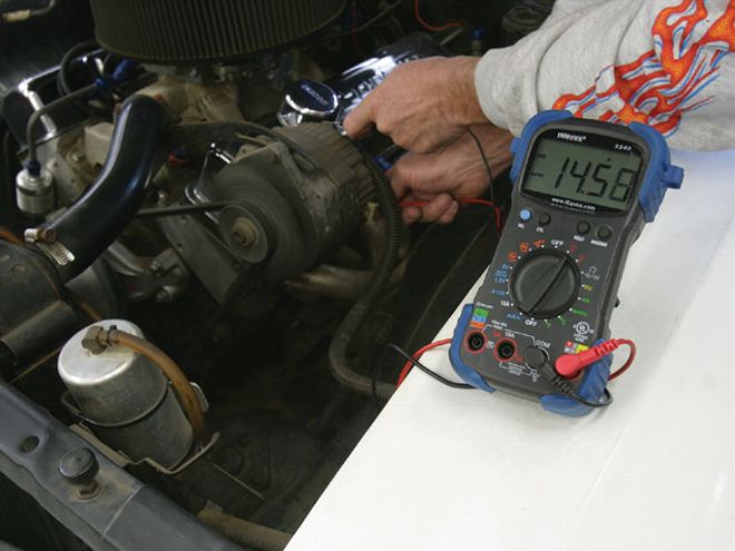 The most accurate test for charging-system efficiency is to start the engine, test the voltage at the back of the alternator, and compare that reading to the voltage at the battery posts. If you see more than a 0.4-volt drop at the battery (14.7-13.9 volts, for example), there is excessive resistance in the circuit. Begin looking for connections that have suffered excessive heat or are corroded.
Charge It
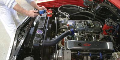
In the musclecar days, a typical car came with a 60-amp alternator, a separate regulator, and perhaps an entire electrical load of 30 amps with the heater and headlights at full song. But today, it's not unusual for a typical street car to be fitted with a pair of electric fans (30 amps). Add an electric fuel pump (8-15 amps), a CD ignition (6-10 amps), and even airbags with a compressor (20-30 amps), and the electrical load at idle could easily equal 60-80 amps. Now add a corroded cable or connection and a 40-year-old charging system harness, and you have a recipe for an excessive load on that original alternator and a quick drain on the battery when the voltmeter dips below 11 volts. But before you instantly blame the alternator, try performing a simple charging-system test. Start the engine, put a load on the alternator by turning the heater and headlights on, and use your fingers to feel the main charging-system circuit between the alternator and battery for unusually warm connections. Resistance builds heat. The hotter the connection, the more current and voltage are being lost. We discovered that the main charge wire connection next to the battery on our El Camino felt warm where the stud and wire connectors had corroded. A simple cleanup fixed the problem and improved our charging-system performance. Following are a few basic diagnostic steps you can take to cure your charging-system ills.
Tech Tip: Never disconnect a battery cable to test the output of an alternator with the engine running. The voltage spike could permanently damage the alternator.
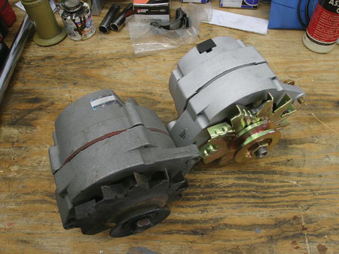
Even the best '60s alternators were not designed to generate maximum output at idle. At best, a 60-amp external regulator alternator (left) can output perhaps 40 amps at idle. We knew that fitting our Chevelle with a pair of big, 12-inch Spal electric fans was going to tax the charging system with a minimum current draw of 40 amps with the fans running, so we opted for this Powermaster 12Si 100-amp alternator that can muster as much as 90 amps at idle and 118 amps at full output. Powermaster tests each alternator for output before it goes out the door.
Alternators rated between 85 and 105 require heavier six- to four-gauge cables to the battery. On '60s GM cars, this means routing a larger gauge wire from the alternator to the horn relay and all the way to the positive battery terminal, including that small insulated terminal block next to the battery.
What's All This Fuss About One-Wire Alternators?The Powermaster people tell us that the most asked tech question is: "How do I hook up a one-wire alternator?" One-wire alternators are becoming increasingly popular in modified cars as well as typical street cars due to their simplicity. The only wire that needs to be connected is a cable from the large output terminal on the alternator to the battery. One-wire alternators begin charging using a circuit that senses internal voltage once the alternator is spinning fast enough. This is why one-wire alternators require the engine to be revved past roughly 1,500 rpm to begin charging. Once energized, one-wire alternators will charge at idle no problem. Factory three-wire alternators use 12 volts from the ignition switch to energize the charging circuit, which is why these alternators begin charging the instant the engine is running. Most aftermarket one-wire alternators are designed so they can be used as either one-wire or three-wire installations.
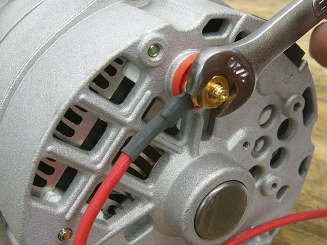
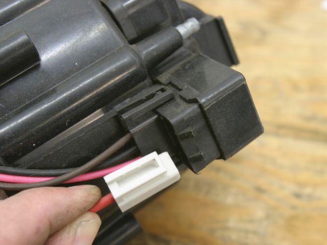
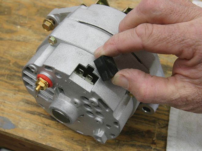 The large red wire that leads to the positive post on the battery to the output terminal on the alternator is the only connection necessary for a one-wire alternator. By removing this black plug, most one-wire Powermaster alternators can be converted to three-wire installations, which is preferred if you have a choice.
What's All This Fuss About One-Wire Alternators?
The Powermaster people tell us that the most asked tech question is: "How do I hook up a one-wire alternator?" One-wire alternators are becoming increasingly popular in modified cars as well as typical street cars due to their simplicity. The only wire that needs to be connected is a cable from the large output terminal on the alternator to the battery. One-wire alternators begin charging using a circuit that senses internal voltage once the alternator is spinning fast enough. This is why one-wire alternators require the engine to be revved past roughly 1,500 rpm to begin charging. Once energized, one-wire alternators will charge at idle no problem. Factory three-wire alternators use 12 volts from the ignition switch to energize the charging circuit, which is why these alternators begin charging the instant the engine is running. Most aftermarket one-wire alternators are designed so they can be used as either one-wire or three-wire installations.
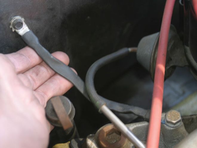 A good ground cable between the battery and the engine is essential, but so are several additional grounds between the engine and the body and the body and the frame. There was a good reason the factory placed those ground straps between the engine and the body. So now you should replace all those straps that you removed before you knew better.
Go to Ground
Electrical systems are very simple. For all domestic, 12-bolt negative ground circuits, you have a power (+) side and a ground (-) side. The most basic circuit feeds power through a wire to the load, like a light bulb, and then must complete the connection back to the negative side of the battery. Without this return side of ground, the circuit is incomplete, current will not flow, and the bulb will not light. What most car crafters overlook is the ground side of the circuit. We've seen this happen to all kinds of circuits, such as with a simple electric fuel pump wired with an adequate 8-gauge wire on the positive side but then handicapped with a tiny, 14-gauge ground wire. The ground wire was badly corroded from heat and severely limited the output of the electric pump because the smaller ground could not support the current draw back to the battery.
We've also experienced bad grounds in our Chevelle after installing a set of electrical gauges. We noticed that with the engine running, when we turned the headlights on, the in-cockpit voltmeter would drop roughly half a volt. Plus, switching the headlights on would make the engine temperature gauge read higher by 10 degrees. Clearly, we had a poor ground between the body and the battery because all those factory ground straps between the engine, body, and frame had long since disappeared. We fabricated several new grounds among the body, frame, and engine, and the voltage fluctuation (and resistance) disappeared. More importantly, both the temp and voltmeters are now more accurate.
Tech Tips
Electrical problems are often very difficult to track down. We've run across many of these that are especially common with muscle cars. One of these might save you a few hours of grief.
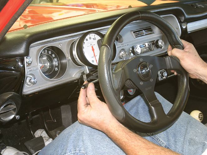
If your '60s GM musclecar has a left brake light that seems to have a mind of its own, take a look at the turn-signal switch. A weak turn signal switch will allow the turn signal lever to drop slightly, disabling the left brake-light circuit. The best fix is a new turn-signal switch.
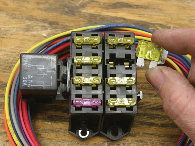
Rather than plug extra circuits into that original, overloaded fuse box, why not just add a new six-circuit box like this Painless unit? The new box features blade-type fuses and plenty of wire to do almost any job.
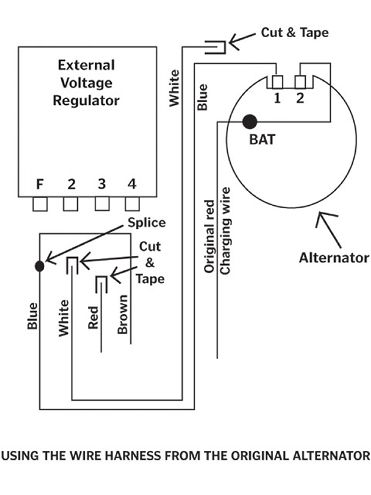
Want to convert that GM '60s vintage, external regulator alternator to a more modern 12Si internal-regulated alternator and retain the warning light on the dash? The simplest route is to plug an M&H Electric Fabricators adapter (PN 27555, $19.00) into the four-terminal harness from the regulator. The cheapest route is to make a jumper wire to connect the blue and brown wires at the connector. Then follow the circuit changes on the drawing for the white wire and the No. 2 wire from the field to the BAT terminal and you're good to go.
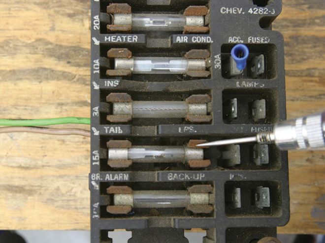
Those '60s glass tube fuse boxes used bare metal clips that have been slowly corroding for 40 years. When checking for a bad fuse, make sure to place the test light probe on the clip rather than the actual fuse. Oftentimes, the fuse is good, but because the connection is so rusty, no power is available to the circuit. This is a common problem. You can attempt to clean the clips, but the best solution is a new underdash wire harness and fuse box from M&H Electric Fabricators.
When swapping an HEI distributor into a musclecar that was originally equipped with points, be sure to use an actual 12-volt switched power source for the distributor. The original factory wires were resistance wires that reduce the voltage to around 6 volts and may not even allow the HEI to operate. Run a wire from a nonfused, 12-volt source on the fuse box that is controlled by the ignition switch. MAD Enterprises offers a simple kit (PN HEI-1, $18.95) that includes the wire and the special power and tach factory-style connectors.