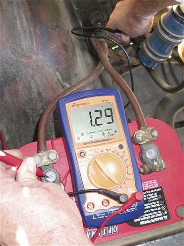
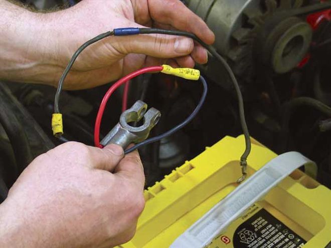
 This weak battery ground cable tested with a high 1.29-volt drop. It hadso much internal resistance it was hot to the touch after only two shortcranking sessions. Heat is a good indicator of a high resistance. With anew, large-diameter MAD battery cable and connectors, the voltage dropimproved to 0.1 volt.
1. BAD GROUNDS
It's standard: You overkill the positive side of the 12-volt circuit andignore the ground circuit. Basic electrical circuit design requires acomplete path back to the battery through the ground circuit, and if ithas high resistance, then the electrical device will operate poorly.
Bad grounds happen everywhere, but the worst case is when guys relocatethe battery to the trunk, run a nice, thick multi-strand cable from thebattery to the starter solenoid, then merely bolt the ground cable tothe trunk floor or other easily accessible spot and leave it at that. Avoltage-drop test (see page 58) on that ground circuit will probablyreveal an inexcusable 1.5- or even 2-volt drop across the ground side ofthe circuit. The starter may crank when it's cold, but not onceeverything warms up (remember, resistance increases with temperature).The fix is to either run a large ground cable all the way up to theengine, or a large ground from the battery to the frame and another fromthe frame to the engine.
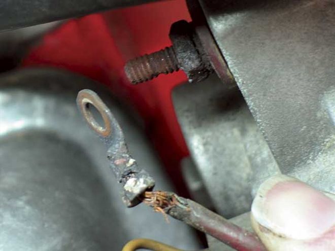
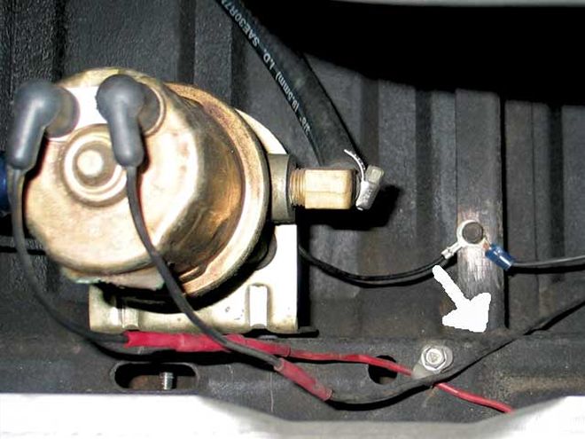 This melted ground wire (arrow) is a sure sign of excessive heat andthat this small wire is carrying too much load. Additional groundcircuits will alleviate overload situations and prevent a fire due to anoverloaded ground circuit.
Another common grounding failure is an electric fuel pump pulling 4 to 5amps. We often see pumps wired with a small, 14-gauge positive cable andfurther crippled with a corroded piece of piano wire for a ground.Improve the ground circuit with a larger 12-gauge wire and ensure thatthe ground circuit offers no more than 0.1-volt drop and the fuel pumpwill run much more efficiently.
The most dangerous bad ground comes from weak or small-wire groundsbetween the engine and the chassis and between the chassis and the body.These create resistance that can quickly overheat and in extreme casesbegin to melt and catch fire. It sounds implausible, but keep in mindthat the ground circuit must complete the current flow, so the groundside must always be as bulletproof as the positive side of the circuit.
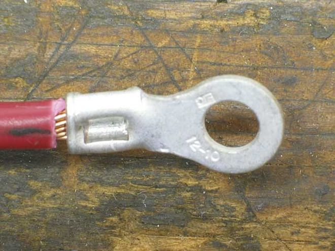 Trim the wire to fit just inside a non- insulated crimp connector. Besure to slide a length of shrink wrap over the wire first, then crimpthe connector as shown.
2. MAKIN' THE HOOKUP
Every auto parts store in the country offers those cheesy crimpconnectors with the little plastic sleeves that are supposed to providea great connection. The problem is that these temporary fixes soonbecome permanent. Certainly one of the least effective electricalconnectors has to be that one that pinches two parallel wires, hoping tomake a connection. If you find one of these connectors in your car, cutit out immediately. And when you get them in the box with a newelectrical goodie--especially a nitrous system--chuck them as far as youcan.
There is some controversy over the proper way to make an electricalconnection. Fans of solder will tell you that it prevents corrosion, butits detractors say it's too brittle and will eventually fail immediatelyadjacent to the connection. The problem with crimp connections--evenwhen protected with shrink wrap--is that they are sources for corrosion.Either way, the following steps outline the right way to perform anelectrical connection.
3. ALTERNATOR CHARGES LESS THAN YOUR GIRLFRIEND
 Using a larger 8-gauge charge wire between the alternator and thebattery improved alternator performance dramatically. It didn't hurtthat we also eliminated three splices in the wire between the batteryand the junction block.
Often the alternator is blamed for poor charging when the problem isactually bad wiring or connections. So try this quickie test. With theengine running, check the voltage at the output terminal of thealternator; on Terry McGean's Camaro, we found a high 15.7 volts. Next,measure voltage at the battery; McGean's was barely 13.5 volts, a lossof 2.2 volts in a circuit that should lose no more than 0.4 to 0.5. TheCamaro suffered from multiple broken strands in the charging wire andseveral corroded connections. We added a large-diameter charging wirefrom a Painless Wiring high-amp alternator kit and improved theconnection between the battery and the junction block using a MADterminal block. Voltage drop across the circuit improved to 0.5 volt.Furthermore, by reducing resistance in the charging circuit, thealternator output voltage dropped back to a more reasonable 14.7 voltswhile voltage at the battery measured 14.2 volts.
4. GANGED WIRES
Let's hope the positive battery post on your musclecar doesn't look likea bowl of spaghetti. Combine that with a typical unsealed battery andthe connections quickly become corroded and nasty. The solution is tomove all those wires off the positive battery post and onto a separateterminal block. MAD offers an inexpensive one (PN CN-1) that canaccommodate several 8-gauge wires to power multiple accessories. This isalso a great idea for an underhood power source for cars with thebattery in the trunk. This block can be used to power up an MSD,electric fans, an A/C, and solenoids for nitrous along with at least adozen other ideas. Hide this under the fenderwell and carefully routeyour wires and you'll be amazed how clean your engine compartment willbecome.
5. HOT-START PROBLEMS
Many slow cranking problems can be traced to high-resistance cables.Using high-quality MAD or Painless battery cables is the obvioussolution. The MAD cable is impressive 1/0 gauge multi-strand copperconductor that is also double insulated. If the starter just grindsslowly, this is a voltage-drop problem. But if you've got the typical GMproblem of the starter not engaging properly in a hot-soak condition,the cause is a major voltage drop across the solenoid-engagementcircuit. The fix is as simple as using a Ford-style external solenoid ina kit from either MAD or Painless. The idea is simple: Mount thesolenoid away from exhaust heat, which radically reduces the voltagedrop across the solenoid circuit. Both kits also supply a shunt thatconnects the solenoid battery cable terminal to the small trigger post.Another advantage is that if you use one of these kits with atrunk-mounted battery, the only time the battery cable downstream fromthe solenoid is "live" is when the starter is engaged. This is a smallpoint, but worthy of consideration from a safety standpoint.
6. ERRATIC GAUGE PERFORMANCE
Have you ever had a set of electric gauges change readings when you turnon the headlights? This is caused by a poor ground circuit, a powercircuit that cannot handle the additional load, or both. Most '60s carsprovide power for the wiring harness through a tortuous path leading upto the fuse box under the dash. There are plenty of opportunities forpower loss and voltage drops along the way.
The quick fix is to improve the ground path between the instrumentcluster and the battery by adding those ground straps you threw awaybetween the engine and the firewall. Then add one or two between theinstrument panel and the firewall and see if the performance improves.
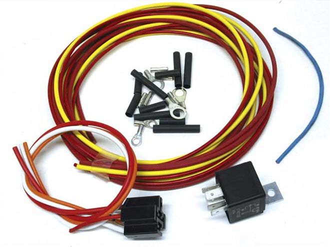 The Painless and MAD basic relay kits use a Bosch or similar relay thatalso includes a plug-in harness and lengths of wire you can use toconnect the relay.
7. RELAYS RACE
If you've ever run a wire from that poor overloaded fuse box to power upan electric fuel pump, or if you've used a large wire from the batteryto a switch and then to a heavy-duty electrical load like an electricfan, there's a better way to go than large clunky switches. Relays are ahandy heavy-duty switching device that can be activated by a very lowvoltage switch. In fact, computers use relays to controlhigh-current-draw items like electric fans and electric fuel pumps.
Here's how relays work. Let's say you're going to bolt on a 20-ampelectric fan. You could run a large 8-gauge wire from the battery allthe way up to a switch under the dash and back to the fan. Instead,mount a relay between the fan and the battery. This creates a shorterpower path from the battery to the fan through the relay. Then you canuse any light-duty switch to control the fan. Relays also work well forreducing the voltage drop on '60s GM car headlight circuit. Mount a pairof relays near the headlights and eliminate the long power path throughthe headlight switch. This shorter path through the relays puts muchmore voltage to the headlights, making them much brighter.
8. UNDERDASH POWER
How many wires do you have jammed into that overloaded fuse box underthe dash of your street machine? Most musclecar electrical systems werenever intended to handle great electrical loads. So when you startjamming more wires into those "switched" and "unswitched" fuse-boxpositions, this greater load could eventually cause problems. Not onlythat, but it just looks cluttered.
The solution is to use a couple of MAD's terminal blocks, one forconstant battery power and the other for "switched" power when theignition key is on. The key is to mount two terminal blocks on a commonaluminum mount located under the dash near the stock fuse block. Thebattery live terminal can pull power directly from the junction blockoff the battery under the hood. The second terminal can be switchedusing a relay triggered by a "switched" terminal on the fuse block. Thebattery live terminal should be protected with a fusible link locatedunder the hood. Now you can bundle all those cockpit accessories tosource power from these two terminal blocks and not overload the stockfuse block. If you really want to be safe, design a clear plastic coverfor the terminal blocks so there's no way to accidentally short theblock to ground.
9. ONE-WIRE ALTERNATORS
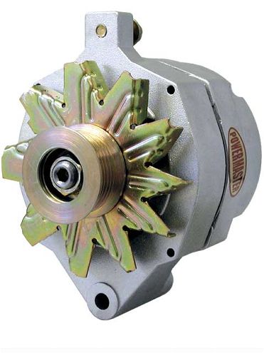 One-wire alternators are certainly the easiest to connect. All you do isdial in a large alternator wire between the output post on thealternator and the positive battery terminal, employing an externaljunction block next to the battery for a cleaner installation.
There's confusion about aftermarket one-wire alternators versus typicalthree-wire alternators. A typical production-style three-wire alternatoruses a voltage sensing wire connected to a main power distribution pointin the wiring harness. This "sensing wire" allows the voltage regulatorwithin the alternator to read electrical system voltage resulting inproper voltage delivery to the wire harness. A three-wire alternatoralso has a special switched "turn-on" wire, and this wire can also beused to operate a warning light at the dash. A one-wire alternatorrequires internal voltage created by the spinning alternator to triggeror start the charging process since it does not have a voltage-sensingtrigger connection. When the engine is started, a one-wire alternatormust achieve a certain speed in order to reach that internal voltage.Once that occurs, the one-wire alternator will begin charging and willcharge even at very low engine speeds. This means you must simply revthe engine above a given rpm (usually around 1,500 depending upon thepulley ratio) before the alternator will begin to charge.
According to a rather substantial treatise on one-wire vs. three-wirealternators on MAD's Web site, the voltage drop from the alternator tothe battery with a long wire can compromise the performance of theone-wire alternator compared to a three-wire. This is why MAD recommendsusing the GM 10Si or Cs130 alternators, even in many Ford applications.This is not a condemnation of the one-wire alternator. But if you wantthe most from an alternator, the three-wire version is slightly moreefficient.
10. FUSIBLE LINKS
 Fusible links are generally smaller than the wiring harness they protectand are designed to melt under a sustained high-amp direct short,protecting the harness from damage and electrical fire.
What the hell is a fusible link? Think of it as a safety net for yourelectrical system. Most domestic cars from the mid '60s through the '70ssource all the electrical power for the car (except for the starter)from either the main charging harness or, in the case of GM cars, fromthe smaller wire pulled directly off the positive battery terminal. Toprotect the wiring harness, most of the car companies used aninexpensive wire called a fusible link that is designed to melt when thecurrent demand exceeds a given level, like from a direct short. Thisprotects the wiring harness from damage, but also immediately disablesthe car. Often, ignorant wire hackers set the car up for a potentialwiring meltdown and subsequent fire by eliminating this fusible link.
If your GM car is now equipped with a fusible link, you can purchase aninexpensive replacement from MAD in 12-, 14-, 16-, and 18-gauge sizesdepending upon the circuit they are protecting. It's also a good idea toprotect individual circuits with their own fusible links. Fusible linksare sized to protect a circuit four wire sizes larger. Also rememberthat larger gauge numbers indicate a smaller wire. So a 14-gauge fusiblelink would protect a circuit using larger 10-gauge wire.
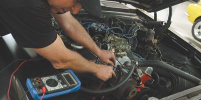
Voltage-Drop Test
This one simple test will tell you more about any specific electricalcomponent than any other test you can perform. The idea is to measurethe amount of voltage that is lost while the circuit is in operation.What we're really doing is using the voltmeter to learn the amount ofresistance in the circuit without having to remove any components, butcurrent must be flowing at the time of the test.
 We performed a simple voltage-drop test on this battery-output cablewith the engine running. Our multimeter indicated a 2.3-volt dropbetween the alternator and the positive battery terminal. This ishorrible, since it should be closer to 0.4 volt.
To begin, set the multimeter on the lowest voltage setting--most oftenthe 20-volt scale. Let's say we're going to test the amount ofresistance in the negative battery cable. A high-quality cable with agood connection should only have about a 0.1-volt drop across itslength. To test it, place one probe on the battery end of the negativecable and the other probe on the end of the cable where it's bolted tothe engine. Disable the ignition system so the engine doesn't start,then have a helper crank the starter while you watch the multimeter.During cranking, current will flow through the circuit, and thevoltmeter will indicate a voltage. If you measure more than 0.1 volt,there is high resistance in the circuit. You can also narrow your focusas much as you wish. For example, to find the resistance in just theconnection between the battery and the cable, place one probe on thebattery post and the other on the cable end, then crank the starter. Ifyou see more than 0.05 volt then the connection is poor.
A higher voltage measured with the voltage-drop test means greaterresistance. Increased resistance means the electrical system isdelivering less power (current) to the load, like the starter motor,headlights, or electric fan. The more power you can deliver to the load,the more efficiently it will operate. It's just that simple.
Volt-Drop Values
* The voltage-drop spec between the alternator and the battery is thetextbook maximum. However, many factory wiring systems get around thisspec by using a main "buss-bar" for central power distribution. Thisversion routes the alternator output and the voltage-regulator sensingwire directly to the buss-bar. In this layout, electrical systemperformance relies upon voltage level at the buss-bar not at the batteryor alternator. This means a voltage drop greater than allowed by theabove spec may not indicate a problem. Chevy musclecar-era systems wereequipped with this layout with a higher acceptable voltage-drop spec.There's more specific information on this topic atwww.madelectrical.com.