
Manual steering gears predate the Model T era. The typical layout is a column and shaft leading from the steering wheel to a frame-mounted gear mechanism. This steering shaft rotates left and right, turning a cross-shaft within the gear. The cross-shaft rotates the pitman arm, and depending upon the front axle layout, the pitman arm moves either fore-and-aft or laterally.
 Mid-'60s Ford manual steering uses Saginaw's recirculating ball-and-nut engineering. Ford trucks relied on Gemmer worm-and-roller steering from 1937-60. The transition to ball-and-nut steering was an improvement in efficiency and dramatically increased the longevity of manual steering gears.
The manual gear mechanism can be a worm-and-sector, worm-and-roller, cam-and-lever, or recirculating ball-and-nut design. In each type gear, the aim is to: 1) Change the direction of steering input motion by 90 degrees, and 2) Establish a steering ratio between the input shaft and the cross-shaft. Although mechanisms differ, the function remains the same: convert steering wheel input into pitman or steering arm rotation. Linkage connects the pitman arm to the steering arms and knuckles at the front wheels.
Types Of Manual Gears
In concept and basic design, manual steering gearboxes have changed very little in the past century. Prior to 1972, several American manufacturers produced manual steering gears. Despite similar outward features, these gears have different internal mechanisms. Let's discuss these components and steering gear terminology.
The worm/worm shaft/worm gear can be a spiral, screw-like gear or a spiral groove machined into the steering shaft. Some worms engage directly with the sector or roller teeth. On recirculating ball-and-nut gears, the worm is a machined, spiral groove in the steering shaft. The groove serves as a ball bearing race. In a cam-and-lever gear, the worm is a cam designed to move the pins of a lever shaft. When the steering wheel turns left or right, the worm or cam rotates clockwise or counterclockwise.
 A 1925 patented Ross single pin (cog) cam-and-lever steering was popular on Dodge, Graham-Paige, Reo, and Mack trucks. Ross built cam-and-lever steering gears as late as 1971. In their best form, the heavy-duty truck versions of these gears had twin studs that rotated on double-tapered roller bearings. I-H, Studebaker, and others used Ross gears.
The sector, pitman shaft, cross-shaft, or lever shaft rotates the pitman arm. Though subtly different by design, each of these shaft types lay perpendicular to the centerline of the input or worm shaft. Supported by bearings or bushings, the shaft has splines and a nut at its outer end. The pitman arm attaches to these splines. Movement of the worm shaft rotates the sector/cross-shaft.
Various patents apply to manual steering gear designs. Manual steering gear terminology frequently associates a design with its manufacturer. These terms and names can be useful when describing or ordering parts for a manual steering gear.
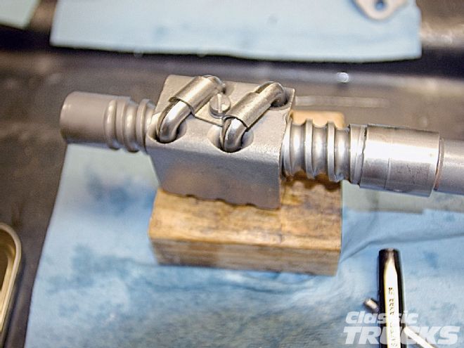
Ross cam-and-lever steering uses a steering column tube or input shaft with a cam at the bottom. This worm cam resembles round bar stock with a spiral groove machined into the cam. A lever is at the inner end of the lever shaft. Pins on the lever engage the cam groove. At the outer end of the lever shaft, splines attach to the pitman arm. The lever pins move with the steering wheel and cam rotation, swinging the lever shaft and pitman arm clockwise or counterclockwise.
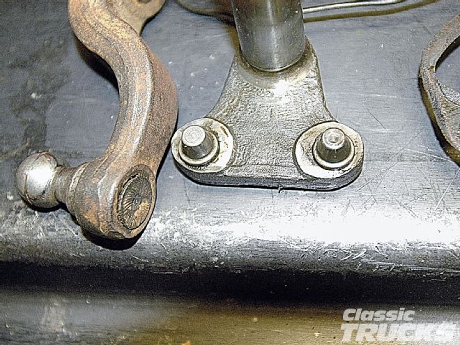
 This Ross twin-pin lever shaft is common to vintage Jeep trucks, I-H Scouts, and Studebaker. Pins do not rotate. Over time, these pins develop a pair of flats at opposite sides of each cone. Compensating with an adjustment is risky and simply borrows time. This gear needs a new lever shaft and bushings.
Ross cam-and-lever gears are common to Jeep, International-Harvester, and Studebaker trucks. The heyday of Ross gears was the pre-war period to mid-'60s. Primitive and wear-prone, light-duty Ross cam-and-lever gears have fixed lever pins and a higher friction factor than other designs. Heavier-duty Ross gears mount the lever pins on bearings. Those designs are available in both single- and twin-stud versions.
Gemmer worm-and-roller gears were popularized in '37-up Ford cars and truck models. The predecessor of the worm-and-roller was Gemmer's worm-and-sector gear. Vintage Dodge pickups also use this gear type. The roller rides on needle bearings and mounts on a shaft at the head of the sector. This rotating roller engages the worm. Friction is much less than with a worm and fixed-tooth sector; a fixed tooth design is sliding friction. The roller is a much smoother rolling friction.
Vintage Ford truck owners are familiar with the Gemmer worm-and-roller steering gear. The '37-52 models use a two-tooth roller, and '53-60 F-Series trucks use a three-tooth roller, which adds stamina and provides longer service life. Gemmer worm-and-roller gears have several wear points: the worm teeth, roller teeth, sector shaft bushings, and the upper and lower worm bearings. Due to the popularity of classic Ford trucks, replacement worms, roller sets and other service parts are available.
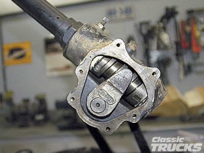
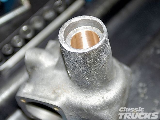
 G.M.'s Saginaw Division pioneered the recirculating ball-and-nut steering mechanism. The nut has ball guide tubes that continually accept and return balls to the spiral-grooved bearing race. Half of the bearing race is machined into the worm shaft (shown). The other half is on the inside of this ball nut.
Saginaw, a division of General Motors, pioneered several steering gear designs. Prior to 1940, Saginaw engineering was similar to Gemmer designs. A worm-and-sector gear was popular on cars and light trucks through 1940. The sector teeth are integral with the sector shaft and do not rotate. Eventually, the worm-and-sector gear teeth develop wear. Minor adjustment is possible with these gears, but significant play indicates the need for a rebuild. Saginaw remedied the friction and wear issue in the 1941-up truck gears.
In 1940, Saginaw pioneered a new steering gear mechanism. Called a recirculating ball-and-nut design, the first application was Cadillac's '40 Model 72. In 1941, all Cadillac models, Buicks, and G.M. trucks acquired this gear type. By the mid-'50s, every G.M. passenger car and truck-whether manual or power steering equipped-came with patented recirculating ball-and-nut steering.
Recognizing the shortcomings and wear factors of a worm-and-sector or roller gear, Saginaw designed a ball nut rack to carry the load. The straight worm shaft has a groove machined into its surface. This precision groove is the inner half of a ball bearing race. Inside the ball nut rack, another machined groove serves as the outer ball race. A set of ball bearings, aided by guide tubes, roll continuously around the shaft and ball nut.
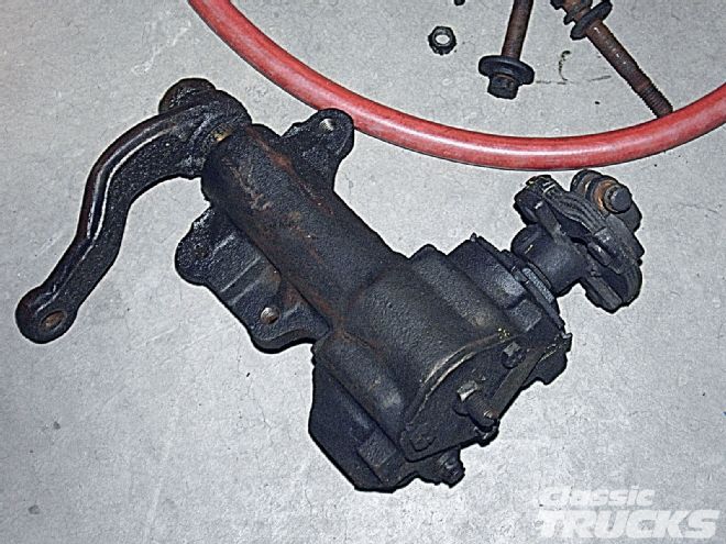 This mid-'60s Ford recirculating ball-and-nut gear uses a splined rag coupler atop a short input shaft (worm). Internals of this gear look much like G.M. versions. Ford cars and trucks use the design beginning in the early '60s. This manual gear was also popular on models with linkage power assist.
The ball bearing fit is precise. As the steering wheel rotates the worm shaft, the ball nut rack glides smoothly up and down the shaft. Teeth on the ball rack engage teeth on the inner end of the sector shaft. Although the sector teeth do not rotate, the ball nut load distributes evenly over the set of ball bearings. The result is smoother, easier steering than a sliding friction or even roller-type gear.
The Saginaw recirculating ball-and-nut steering gear is the best design to date. Foreign and domestic vehicle manufacturers have adopted its features, and Saginaw supplies gears worldwide. Uncomplicated and exceptionally durable, the Saginaw recirculating ball-and-nut gear has been a popular retrofit for street rods, off-road 4x4s, drag cars, and vintage trucks.
Service And Adjustments
Routine service on any manual steering gear is minimal. Factory manuals call for gear lube checks at each routine service interval. Gear lube can seep, creating the need to top off. Typically, the inspection or fill plug is at the top of the gear housing. Carefully clean the fill plug area before removing the plug.
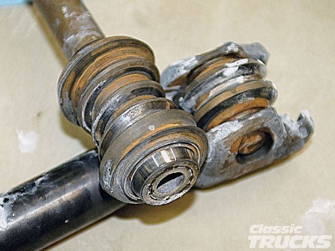
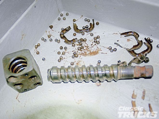 Key to ease of operation on ball-and-nut gears is the ball bearing supported rack (left). The balls move constantly through the tubes and between the worm groove and inner ball nut races. Gliding action dramatically reduces friction and distributes loads evenly. Tapered teeth on the nut and sector are strong and long lasting as well.
Lube should be visible with the plug removed and the truck parked level. Typically, the fill point is the base of the plug threads in the housing. Traditionally, the lube was 80- or 90-weight gear lubricant. Some manufacturers allow a mix of cup grease and gear lube on higher mileage gearboxes. (See the shop manual for recommendations.)
Beware of exhaust headers or a large conversion engine that pours heat into the steering gearbox. Seals and gaskets become brittle, and gear lubricant can stiffen or even burn away. Big-block V-8 installations can present these kinds of problems. For whatever reason, there are no drain plugs on a manual steering gear case. When a gear needs rebuilding, contaminated or scorched oil is often a factor.
Adjustments described in the shop manual can be performed with an accurate spring scale or a torque wrench. Note whether the adjustment calls for disconnecting the steering linkage. Be clear about the center position of the steering gear.
Do not rely upon the steering wheel position to determine the center point of the steering gear. If necessary, disconnect the steering linkage at the pitman arm and gently rotate the steering wheel lock-to-lock. Carefully count the turns. Divide the total by two, and slowly rotate the steering wheel halfway back from one steering extreme or the other. This should be the approximate midpoint or "high point" of the gear.
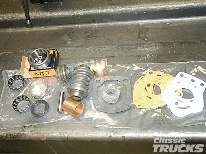 These are the replacement parts for a Gemmer worm-and-roller steering gear. A new roller and worm gear, upper and lower worm bearings, new sector shaft bushings, seals, gaskets, and shim gaskets make up the kit. The roller's shaft requires special installation, as does the worm. If a worm with shaft is available, buy it.
On manual steering gears, the high point indicates the closest mesh of the gear teeth or lever pins. This is the point described in adjusting specifications as the over-center mesh adjustment. Mesh adjustment is read in this zone of steering.
Before checking or adjusting mesh, check the worm or cam bearing adjustment. Ball, barrel, or tapered roller bearings support the upper and lower ends of a worm or cam. If the bearing load or endplay is too tight or loose, make this adjustment. Too tight would only occur if the gear has damage or someone over tightened the bearings. After adjustment, make certain the bearings feel smooth and do not bind. When any more than a slight worm bearing adjustment is necessary, the gear likely needs rebuilding.
Once the worm bearings are set properly, you can test the over-center mesh. Rock the pitman or sector shaft up and down to check for wear at the shaft bearings or bushings. If the sector bushings or bearings are within tolerance (matching the shop manual's specifications for shaft side play), gear tooth or lever pin mesh can be tested accurately. Follow the steps in the manual to measure the over-center mesh. Again, any more than a slight adjustment indicates excess parts wear.
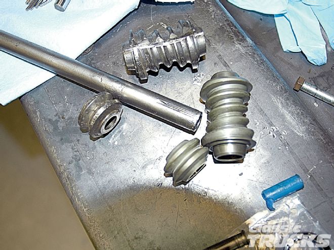 The old worm and roller stands out next to the new parts. The notch in the old worm was carefully cut to relieve tension before pressing the roller off the steering shaft. If you can find a new or NOS sector shaft with the roller already installed, buy it. Ford and others sold the sector shaft and roller as an assembly.
You will discover that manual gears have pitman backlash as you move the steering away from the center high point. Do not mistake this play of the pitman arm for excess backlash. Notice that as you steer back through center, the backlash at the pitman arm goes away. In actual driving, the backlash off-center is not felt. If caster angle at the front wheels is set correctly, there will be no wander from this backlash. The close mesh over-center provides good road feel with the wheels in the straight-ahead steering mode.
A final consideration is alignment of the front wheels with the center point of the steering gear. Everyone wants even steering wheel spokes when the road is straight. However, this is not as important as making sure the high point of the steering gear indexes with the front wheels in the straight-ahead position. Start by aligning the front wheels with a toe-set bar or on a commercial wheel alignment rack.
Find the center point of the steering gear. This may require disconnecting the steering linkage at the pitman arm. If the steering linkage is adjustable, align the drag link or center link so that the steering gear is in its center position when the front wheels point straight ahead. Once the gear is on-center with the front wheels pointed straightforward, you can position the steering wheel correctly.
 New shaft bushings or bearings should be installed with proper tools. Bushings often come unfinished and require reaming. A smart way to do this is a through-type (kingpin) reamer that catches both bushings at the same time. Ream to slightly less than the finished size. Finish the bushings with a piston pin hone or suitable honing method.
On many vintage trucks, the steering wheel can be positioned anywhere in a 360-degree range. Some models have a fixed (woodruff keyed) steering wheel location. When the steering gear is on its high point, the steering wheel is straight. There is usually a provision in the steering linkage (an adjustable drag link or center link) for centering the gear's high point while the front wheels point straight ahead.
Any more than a slight mesh adjustment indicates excessive parts wear. Always check for roughness and binding after adjusting the mesh. If gear teeth have chipped or lever pins have worn flat (common on high mileage steering gears), adjustment is futile and risky. The gear may lock up or bind in service. Make plans to rebuild the unit or upgrade to a more modern steering system.
What Did You Learn This Month?
Night School would not be complete without a quiz! Don't worry about your test-taking skills or grades. This is an open-magazine, true or false test. Clues can be found within the Night School text, photos, and captions. Have a good month!
True or False Questions:
1. Rack-and-pinion steering has been popular and available on light trucks since the 1920s.
2. Worm-and-roller steering gears have a recirculating ball-and-nut mechanism.
3. General Motors' Saginaw Division designed the most durable manual steering gear to date. G.M. trucks began using the recirculating ball-and-nut gear in 1941.
4. It's a very good idea to run exhaust headers close to the manual steering gear. This will keep the gear lubricant warm in the winter.
5. Parts are available for rebuilding vintage Gemmer steering gears. The classic '53-60 Ford F-100 pickups use a Gemmer steering gear with a three-tooth roller.
6. Most vintage manual steering gears use an 80- or 90-weight gear lubricant. The steering gear fluid level should be checked when you perform routine lubrication service.
7. The steering gear's high point should line up with the front wheels in the straight-ahead position. This gives good road feel and helps eliminate wander.
8. Your vintage truck wanders all over the road. Steering wheel play measures 120 degrees. This steering gear is not a candidate for minor mesh adjustment. The gear should be rebuilt and adjusted to specification.
9. After adjusting the steering gear, you feel roughness when rotating the steering wheel. There is slight binding in two positions. The gear needs a complete rebuild.
10. The steering wheel lines up with the high point of the steering gear. Driving down a straight road, the steering wheel sits 45 degrees off center. It's okay to just remove the steering wheel and reinstall it with the spokes straight. The high point is not important.
1 false 2 false 3 true 4 false 5 true 6 true 7 true 8 true 9 true 10 false