With plans to install a Banks turbo diesel engine producing more than 500 lb-ft of torque, we knew the nearly 50-year-old Ford 9-inch and drum brakes that underpinned Project Speed Bump were not going to be stout enough for our needs. We were going to need a more robust axle to get our power to the ground reliably, as well as handle repeated launches at the drag strip. In our minds, a Dana 60, with its big 9.75-inch ring gear, seemed like the right fit. After all they were common to 1-ton Fords of the day.
For those who aren't familiar with the Dana 60, the axle is the heavier-duty big brother to the famous Dana 44 and was first used in the 1950s. Over the years, the popular Dana 60 has been found under countless Dodge, Ford, GM, Studebaker, International-Harvester and Jeep 3/4-ton and 1-ton fullsize trucks, as well as Ramchargers and Trail Dusters with the 440ci V-8, and some heavy-duty 1/2-ton Ford and IH trucks. Late-model Dana 60s are typically equipped with 30-spline axleshafts, in either a semi- or full-floating configuration; 35-spline axleshafts are found in some applications from the factory, but are the standard upgrade in the aftermarket.
Axle tubes vary in size from 3 inches to 3.5 inches in diameter, and Dana lists the GAWR as 5,500 lb-ft for a semi-floating axle and 6,000 to 6,500 pounds for the full-floaters. Both versions have a torque output rating of 5,500 lb-ft of torque. The Dana 60's ring gear is 9.75 inches in diameter, and the available gear spread ranges from 3.31:1 to 7.17:1. There are both low- and high-pinion versions, and six- and eight-lug wheel bolt patterns.
Rather than raiding junkyards for an axle we'd have to cut down and modify to fit, we decided to work with our friends at Dynatrac to have one built to our specs. Dynatrac is known for manufacturing some of the finest Dana-based axles on the planet. Built-to-order in Huntington Beach, California, these axles are 100-percent made in the USA - down to the raw materials that go into each housing. Dynatrac also stands by their axles with a very generous warranty.
For Project Speed Bump, we settled on a semi-floating, low-pinion, 35-spline version of Dynatrac's Pro60, with 3.5-inch tubes and the axle flanges drilled to match our Crown Victoria frontend's 5x4.5-inch bolt pattern. We also measured our stock axle to be about 61.25-inches from flange to flange, so we had the Dynatrac axle built with an even 60-inch width, allowing us a little more room to fit a dished wheel on the rear.
Inside the Dynatrac 60, we dropped in 4.10 gears after Gale Banks Engineering calculated engine output of our 3.0L 630T V-6, the 6L90 transmission gear ratios, tire diameter, power curve, and comparing the results against a 3.73 gear. With the 4.10s, we saw a higher average horsepower number and better acceleration, in exchange for a lower top speed and a 230RPM rise in cruising RPM. With this setup, we estimate Speed Bump will hit about 113mph, with the quarter miles passing by in about 12.9 seconds at 100 mph. Respectable numbers for this old driver.
Of course any decent time slip requires the ability to get your tires to hook. For that task we turned to Eaton's tried-and-trued Truetrac limited slip. The Truetrac uses helical gears that have no wearable items, such as clutches or cones, making it easy on maintenance and it doesn't requiring any friction modifier or oil additive. The mechanical differential behaves much like an open differential in normal driving conditions, automatically sending torque to the wheel with the most traction. Because it never truly locks the axleshafts together, it doesn't have any of the quirky driving or handling characteristics that can be felt with a true locker. Other nice features of the Truetrac is that it can be preloaded using a little brake pressure and for those who enjoy a good old-fashioned J-turn, you'll be happy to note that the Truetrac also works in reverse.
Speaking of brakes, we have plans for some serious brake hardware improvements. With eyes on a TCE Performance Products' Wilwood-based 14-inch big brake setup on the front, we wanted to make sure the rear brakes would be a good compliment. After consulting Dynatrac and ensuring a correct fit, we settled on Wilwood's Forged Narrow Superlite 4R Big Brake Kit, with parking brake integration. This kit, designed for the new Ford big-style flange, with an axle offset of 2.5-inches, comes with Wilwood's 12.88-inch rotor Forged Narrow Superlite 4-piston (FNSL4R) calipers and will fit wheel diameters of 17-inches and greater.
The two-piece rotors feature a premium-grade aluminum mounting hat that integrates Wilwood's internal shoe parking brake system. The rotors themselves are 1.1-inches thick and are made from Spec-37 iron in Wilwood's SRP designation. This means a specially engineered directional cross drill and face slot pattern that is said to improve brake response and feel regardless of pedal pressure. The holes and slots provide a cleaning action that helps to reduce pad glazing and unnecessary material has been removed to aid in lower rotating mass and unsprung weight. Both the rotors and hats are electro-coated in black for corrosion resistance.
Clamping down on the SRP rotors are Wilwood's 4-piston FNSLR calipers, the company's newest member of their popular Superlite caliper family. Now utilizing radial mounting with just two planes of adjustment, aligning the caliper over the disc is a simple affair. We ordered our calipers in red (black and polished are also available) and when matched with the 14-inch front brake setup we have planned, will provide Project Speed Bump with exceptional stopping power.
Putting all of these top-notch components together into an axle assembly took less than a day. Follow along as we documented the process of how Dynatrac turns raw materials into some of the best custom axles available.
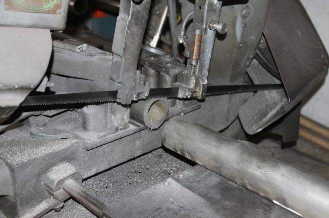
| Project Speed Bump Part 4 Raw Tubes
Our build started by selecting 3.5-inch tube (0.5-inch wall) and cutting it down to the proper length for our axle's custom specifications.
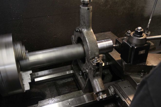
| Project Speed Bump Part 4 Dynatrac Machining
The soon-to-be axle tubes were then moved to the lathe and the ends were machined down.
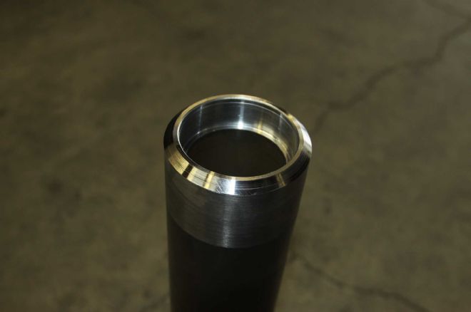
| Project Speed Bump Part 4 Dynatrac Tube Ends
Here is what the flange-end of the axle tubes look like after machining.
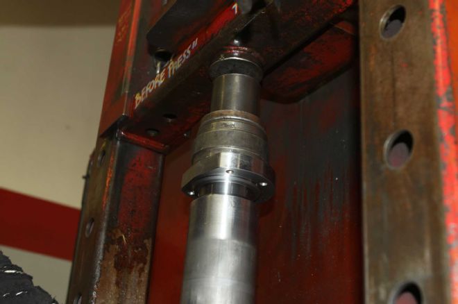
| Project Speed Bump Part 4 Flange Press
Next, the new flange is mated to the axle tube and pressed into place.
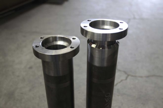
| Project Speed Bump Part 4 Dynatrac Flanges
On the left is a tube with a pressed flange, while the tube on the right is waiting for its turn in the press.
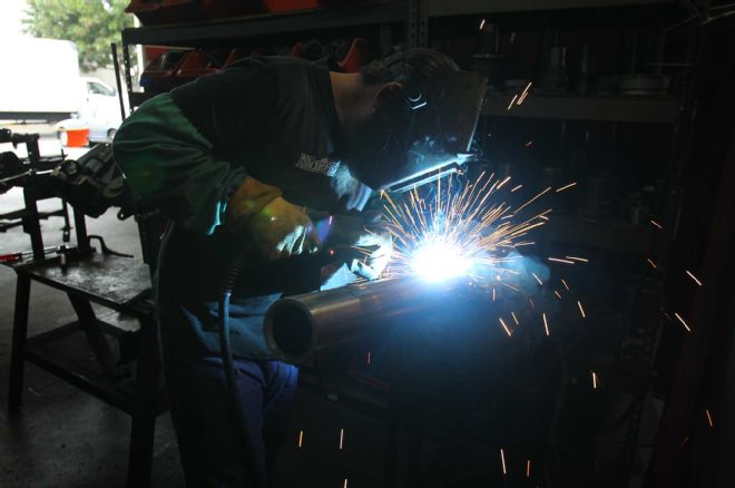
| Project Speed Bump Part 4 Dynatrac Welding
The axle tubes are then moved to a welding station where the flanges are welded in place.
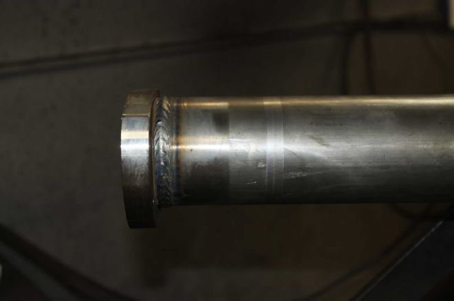
| Project Speed Bump Part 4 Dynatrac Weld Quality
Here is an example of the type of weld quality you can expect from Dynatrac on every axle.
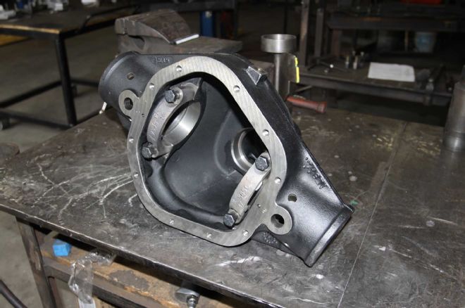
| Project Speed Bump Part 4 Dynatrac Pro60
With the flanges pressed and welded to the axle tubes, it was time to grab our Dynatrac Pro60 housing. Dynatrac offers several types of housing designs, depending on use, including housing designed for IRS cars, such as the Challenger, and special ProRock high-clearance housings for off-road vehicles.
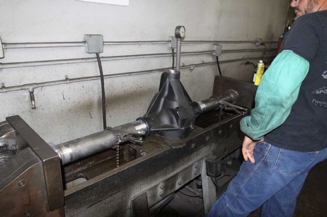
| Project Speed Bump Part 4 Tube Press
Moved to another press, the axle tubes were mated to the housing and aligned for pinion angle (in our case, zero degrees) and pressed into place.
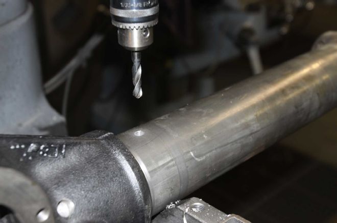
| Project Speed Bump Part 4 Axle Vent
Once off the press, the axle was drilled and tapped for the vent line, as well as brake line junction mounting.
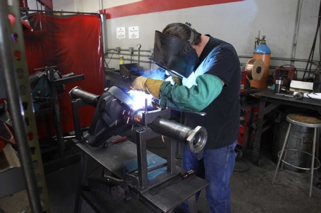
| Project Speed Bump Part 4 Dynatrac Housing Weld
The last step of assembly was to transfer the axle back to a welding station to the inside of the housing where the tubes meet the housing and the exterior plug welds.
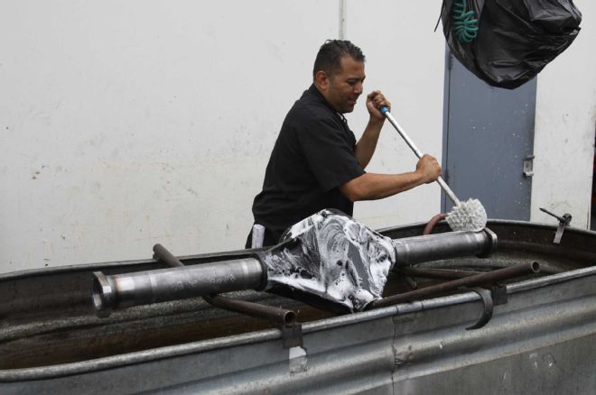
| Project Speed Bump Part 4 Axle Cleaning
Before the axle housing could become an axle assembly, it had to be thoroughly washed, removing any grease or debris leftover from the manufacturing process.
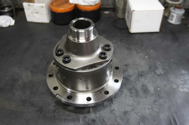
| Project Speed Bump Part 4 Eaton Truetrac
At the heart of our new axle assembly is an Eaton Truetrac helical-style limited-slip differential.
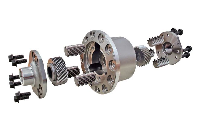
| Project Speed Bump Part 4 Truetrac
In this exploded view, you can see the Truetrac's patented parallel-axis planetary helix gears, which provide the automatic splitting of torque with quiet, maintenance-free operation.

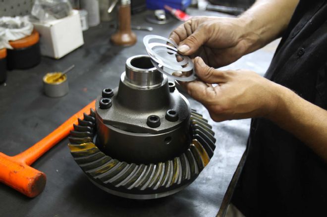
| Project Speed Bump Part 4 Ring Gear
Our next step was to Loctite the mounting bolts and bolt the 4.10 ring gear to our Truetrac, torqueing them to spec on the bench.
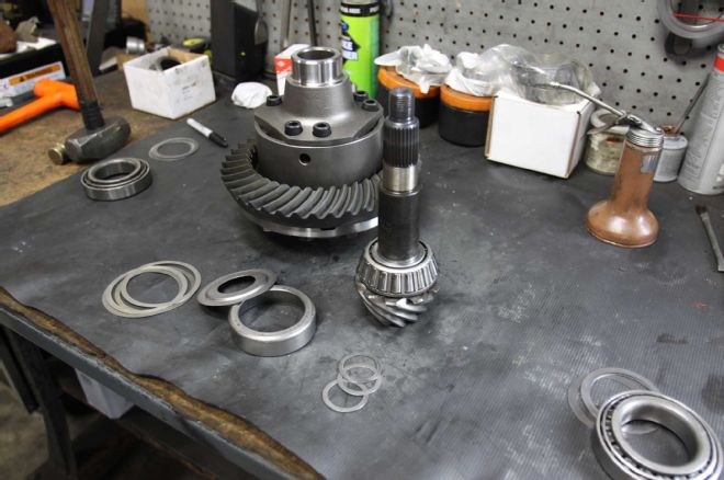
| Project Speed Bump Part 4 Gear Setup Bench
Here you can see the ring and pinion gears, the shims, as well as the races that go into setting up a differential. Setting up gears is a skill that takes years to master, a lot of patience, and a feel for just the right amount of movement.
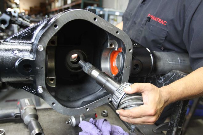
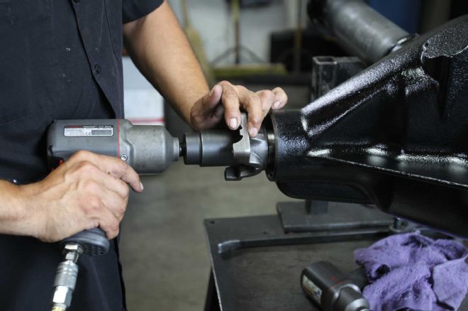
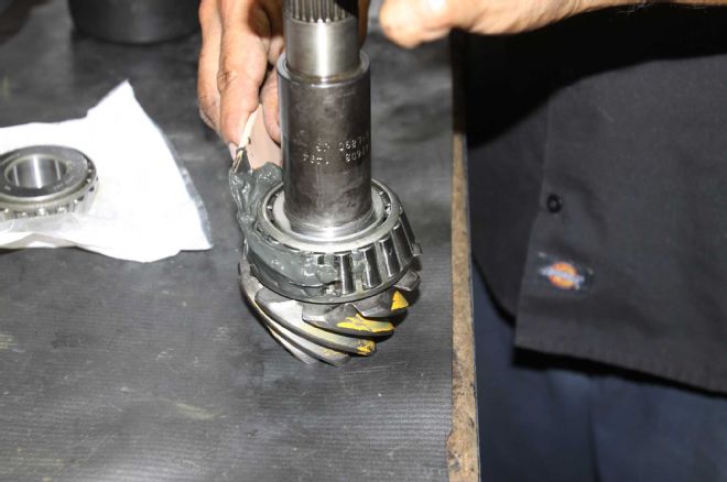
| Project Speed Bump Part 4 Pinion Install
We began our assembly by installing the pinion race and pinion into the housing.
| Project Speed Bump Part 4 Yoke Install
After installing the shim, bearing, and yoke, the pinion nut was tightened.
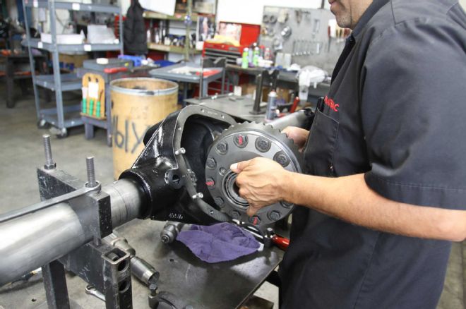
| Project Speed Bump Part 4 Gear Mockup
Next, we mocked up the ring gear assembly with bearings and shims and dropped it into the case.

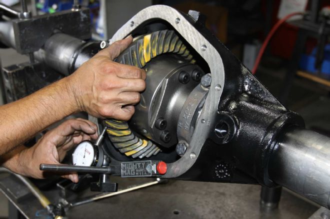
| Project Speed Bump Part 4 Gear Pattern
With the bearing caps installed and tightened, we applied special grease to the gear face and ran the first of several patterns to determine how the gears were meshing.
| Project Speed Bump Part 4 Gear Setup
We pulled the ring gear out, adjusted the shims, and put it back in, repeating the process until we got a pattern we were satisfied with.
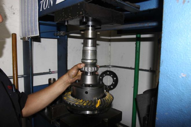
| Project Speed Bump Part 4 Bearing Press
As soon as we were happy with where we were at with our shims and pattern, we began final assembly by pressing the bearings onto the ring gear assembly.
| Project Speed Bump Part 4 Bearing Grease
The housing was then sealed, bearing races installed, and the bearing on both the ring and the pinion were greased.
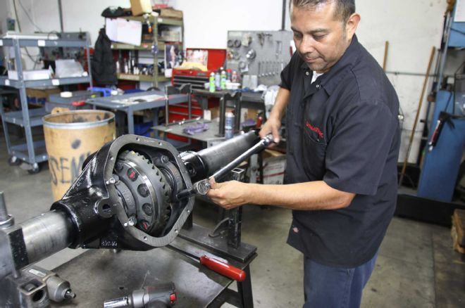
| Project Speed Bump Part 4 Pinion Tool
With the pinion and yoke reinstalled and torqued down, the ring gear was reinstalled and the bearing caps in place. We then took a final check of the pattern reading with the pinion depth tool.
| Project Speed Bump Part 4 Bearing Cap Torque
The bearing cap surfaces were then lubed and Loctite was applied to the threads before being torqued to spec.
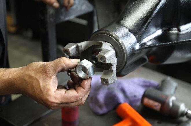
| Project Speed Bump Part 4 1350 Yoke
To ensure years of trouble-free operation, the pinion and nut also received Loctite before the 1350 U-bolt-strap-style yoke was installed and torqued one final time.
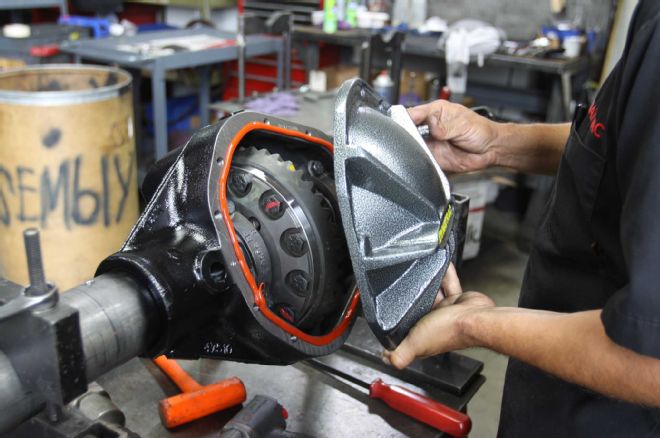
| Project Speed Bump Part 4 Dynatrac Diff Cover
With the gear portion of the install complete, we sealed up the differential housing with a Dynatrac's signature nodular iron differential cover.
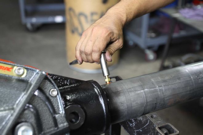
| Project Speed Bump Part 4 Vent Fitting
Here the axle vent fitting is installed into the axle.
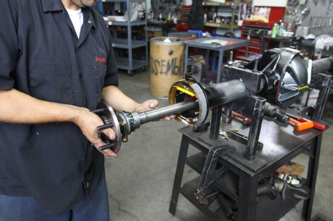
| Project Speed Bump Part 4 Axleshafts
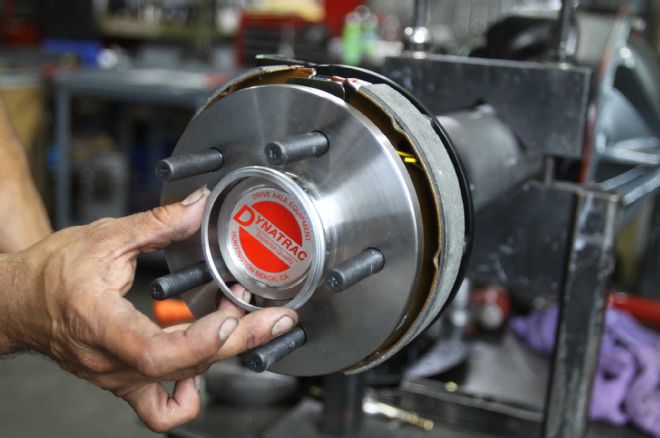
After prepping the axle by installing the races into the tubes and bolting on the Wilwood parking brake assemblies, we pressed the bearing and wheel studs into the axle flange on our American-made 35-spline axle shafts and slid them in to place.
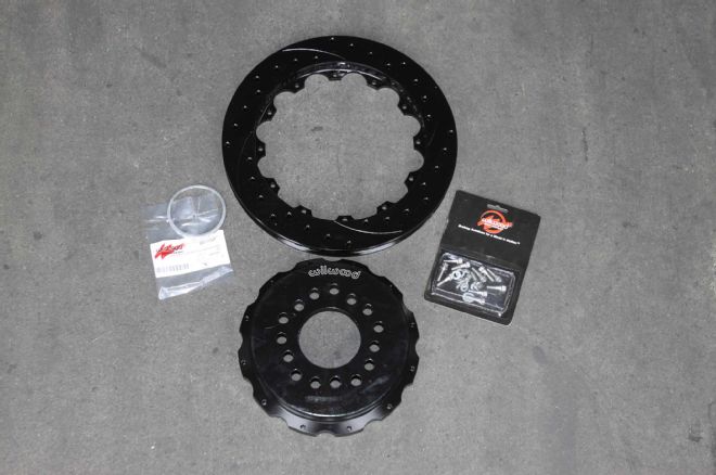
| Project Speed Bump Part 4 Wilwood Rotor Parts
Our Wilwood rotor assemblies consist of an aluminum hat and iron SRP rotor, held together with special hardware and safety wire. The aluminum hat helps to shed heat and contributes to lower rotating mass.
| Project Speed Bump Part 4 Wilwood Register Rings
These Wilwood-supplied register rings, available in different sizes to match whatever axleshaft you are running, perfectly center the rotor and hat over the hub, also known as hub centric mounting. This ensures the rotor is positioned properly for the best performance.
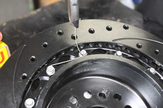
| Project Speed Bump Part 4 Safety Wire
With the axles and parking brake assembly in place, we mated the 12.88-inch Wilwood Spec 37 rotors with the Wilwood aluminum hats and safety wired the hardware in place.
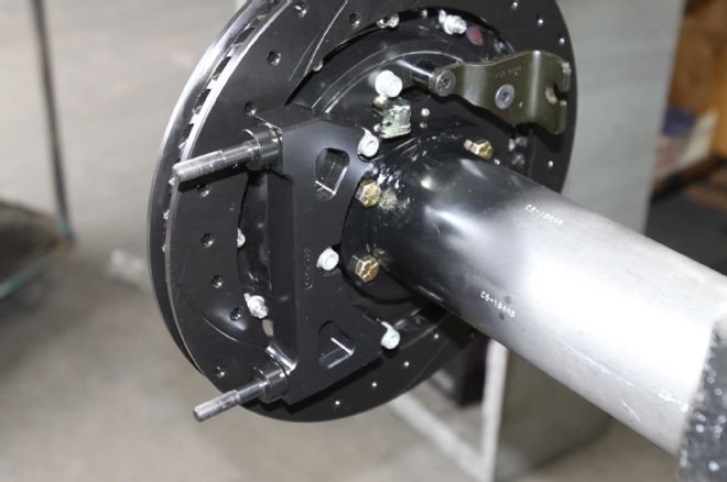
| Project Speed Bump Part 4 Caliper Bracket
Following the placement of the rotors, we mounted the caliper brackets with the supplied hardware.
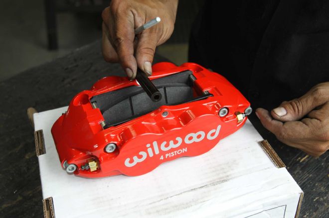
| Project Speed Bump Part 4 Wilwoo 4 Piston
Next, the 4-piston calipers were loaded with brake pads. A nice feature of the Wilwood FSNLR4 caliper is the ability to top load the pads for easy replacement.
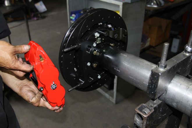
| Project Speed Bump Part 4 Caliper Mounting
Finally, we slid the calipers on to the caliper mounting brackets and after ensuring they were centered over the rotors, we torqued down the hardware.
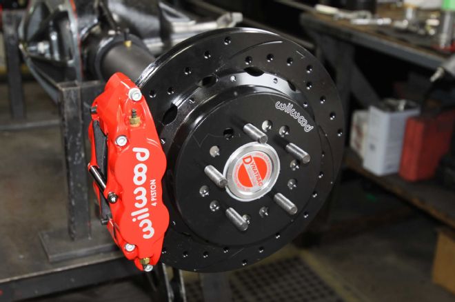
| Project Speed Bump Part 4 Final Assembly
What started out as raw materials and a loose collection of components in the morning, ended up as this masterpiece of mechanical art by the afteroon. While form is sometimes said to follow function, there is no denying we have both with Project Speed Bump's stout new rear axle and brakes.
Check out this short video of the axle tubes being pressed into the Dynatrac Pro60 housing.