Question
 RELAY AND WIRES
Hi, my 2002 dodge grand caravan sport 3.3 v6 is showing
check engine light. Code from key dance is 1491 which
indicates rad fan relay circuit problem, FANS DO NOT RUN.
According to manual it could be relay, wiring or PCM.
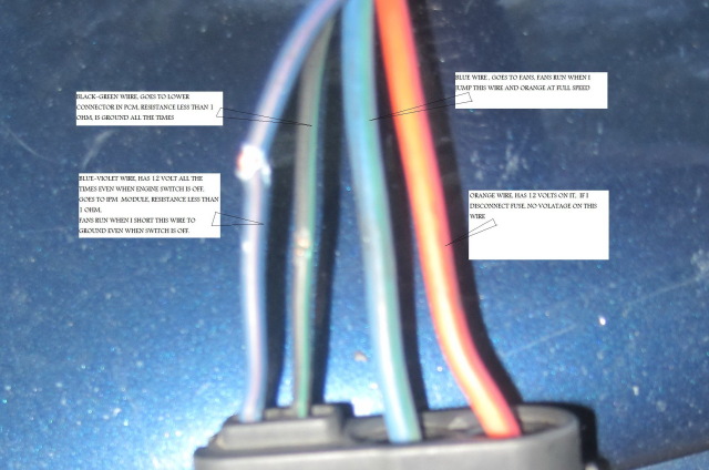
I am attaching an image with all wires going to relay
circuit and with all the voltage on them. fans do run but
draw
16 amp (my multimeter says it can read a max of 10 !, but it
showed 16) when I jump the circuit to them.
I changed the relay and disconnected the battery at same
time. when i started the van again, code 1491 disappeared .
when i turned switch off in 5 seconds and restarted van,
code 1491 came back again.
there are four wires as in image,
Orange/red wire has 12 volts, Fuse is ok, when in DIsconnect
fuse, no voltage on red wire. when i short this wire to
blue/green wire, fans run, resistance between orange wire
and battery positive terminal is less than 1 ohm.
light Blue wire goes to fans,
Black -green wire has ground all the time, with resistance
between this wire and PCM connector is less than 5 ohm.
FAN do not run when i short this wire to ground.
Blue violet wire, has 12 volt all the time, even when switch
is off, fan run when i short this wire to ground, i
could trace it to IPM where resistance is less than 5 ohms.
IF SWITCH IS OFF, AND I SHORT THIS WIRE TO GROUND, NEAR
RELAY, FAN RUN. I COULD NOT SEE A BLUE-VIOLET WIRE GOING TO
PCM CONNECTOR.
AM I TRACING BLUE VIOLET WIRE WRONG, ANY CIRCUIT DIAGRAM
MIGHT HELP.
AnswerHi Mudassar,
You have a good 'handle' on this relay situation. The orange/red is from the 40 amp fuse 27, and the relay, when activated passes that current on the dark blue/dark green wire to the fans.
The black/dark green grounds one end of the relay actuation coil. The coil is actuated when 12v is applied to the other end of the actuation coil via the dark blue/violet wire. That wire connects to pin 1 of the 10-pin green exterior/blue interior plug at the ipm. Inside the ipm that wire jumps to the socket pin 18 of the 20-pin natural color external/red internal plug of the ipm. The wire connected to that pin's plug is brown/violet and that comes from the pcm gray exterior/gray interior 40-pin plug on pin 73. I would believe that this brown/violet wire should be 'cold' except under conditions when the fans are called into play (when coolant temp reaches threshold or ac is requested) at which point the pcm applies 12v to it which should close the relay's points.
I am not quite clear on what you are observing and how that differs with what I have described as this circuit. There has been a history of failure of these solid-state relays so if the wiring checks out I would believe it to be a failed relay. In the latter 90's there was a recall on that relay and perhaps there was also for the '02.
Roland
PS Please 'rate' my answer, and where you see the question about 'volunteer of the month' consider giving a yes response. Thanks