QuestionQUESTION: Greetings Roland, from a fellow 'A-Expert' (tig welding).
I have a problem with our '94 Grand Voyager 3.3L FWD no ABS.
I read a past post you had with title:
You are here: Experts > Home/Garden > Auto Repair > Chrysler Repair > Alternator trouble: voltage spiking high
Chrysler Repair - Alternator trouble: voltage spiking high
Expert: Roland Finston - 2/26/2008
------------------------------------------------------------------
I seem to have a similar issue ( code 41 alternator fail, replaced alternator, still not charging, now code 47) but have a few additional questions:
1. If I am checking the dark green wire on the alternator end, which of the 2 tabs on the alternator is the 'green' one??
2. I read somewhere you can ground directly to the alternator while having a volt-meter hooked to your battery and test if the regulator/ECM(#4686777) is the culprit in the system.
Is this correct??
If so, would I need to take off any of the attachments to the alternator to do this?
Is it safe?
Thank You in advance,
Dean Stewart
ANSWER: Hi Dean
The wiring diagrams show there to be 4 wires: the red wire is the output that goes to the battery, and it is shown to be on a longer 'extension', the black wire is a ground wire for the case of the alternator that is attached to the nearby heated oxygen sensor, and that wire is show to be near the base of the red wire's extension. Then the two side by side tabs are the field coil wires: the one that is closer to the first two I described should be a dark green/orange wire which is a 12v supply wire from the autoshutdown relay, and the further tab is the dark green no stripe wire which is the wire that comes from pin 20 of the pcm and is oscillated to ground by the pcm at a frequency such as to produce the desired output voltage on red wire. If you remove the dark green wire and ground the tab with a jumper by hand you should see the voltage on the red wire spike to maybe 16+ volts, but don't leave it that way for any longer than a moment, just touch it to verify that it is controlling the output voltage. If it doesn't, then check that you have 12V on the dark green/orange wire while the engine is idling #ASD relay closed therefore#*. If you do, then there is something wrong with the alternator, if you don't then the wire from the ASD to the alternator is "open". The field coil has the have a 12v supply on one end and a ground connection (oscillated or momentarily touched to ground) for there to be any current put out by the armature.
Roland
*In fact you might be wise to verify that you do have 12V on the dark green/orange before removing the dark green wire as without that voltage you can't generate a magnetic field in the field coils.
If you do get a voltage spike, then the alternator is good, and so the next thing to check would be that you have continuity between the dark green wire at the the alternator and its other end at the pcm. It does pass through a 4-wire disconnect located behind the battery so be sure that has been opened up. If you have continuity then one would believe that the pcm is not doing its regulating function.
---------- FOLLOW-UP ----------
 '94 GV Alt wiring
QUESTION: Hi Roland and Thanks for the much needed assistance.
Your call on the wire colors is 'spot-on'!
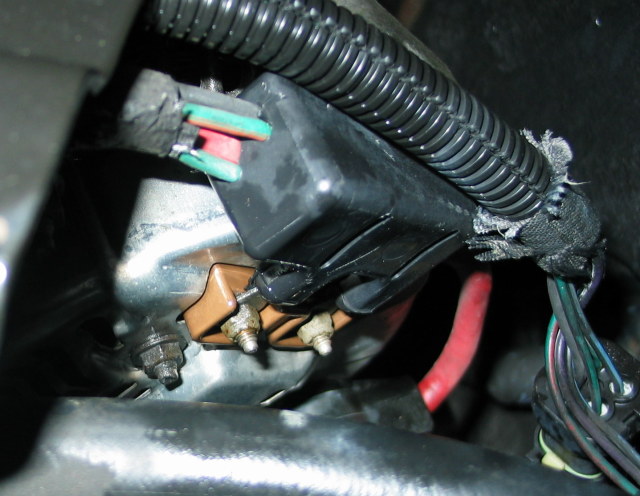
I have included a pic of my alternator for help.
A few more questions here to clarify.
1. The wires come together in a black block on the back of the alternator.
Apparently the black wire goes to the tab facing the firewall and is screwed to the alternator chassis as you described. Correct?
2. The green/orange being closest to the black and red wire attachments would be on the right as we look at it, closest to the firewall. Correct?
3. How would I remove the dark green wire without removing the whole black block??
Would I need to cut the green wire before the block?
Would I need to remove the tab off the post or just ground to the post on the alternator??
4. Would I check the voltage jump at the battery posts with my volt-meter?
The alternator is brand new. Before I was getting a code 41.
Now I am getting a code 47. Arrrrgh!!
5. To verify I have 12v at the grn/org, would I run my tester from the stud on the grn/org to ground?
6. To check continuity, should I take the block off the alternator and run an ohms test on that wire??
7. Is there a diagram that shows which pin is #20. My Haynes does not show it.
Thank You again Roland.
PS - I have many hundreds of thousands of miles in these vans I run 2 of them continually for work. I do most all of my own car work, only if I am swamped will I allow anyone else to touch any of our cars.
I have quite a few 'tricks' I have learned and with regular maintainence, we put massive mileage on these vans at a very reasonable cost.
If there is anything I can help with, I would be more than happy to assist. I do not think I would qualify as an expert here, unless there is a very specialized area for generation 2 Chrysler mini-vans.
Thanks again
Dean.
AnswerHi Dean,
Thanks for the photo, and offer to assist. Let me take the questions in order:
1. The wires come together in a black block on the back of the alternator.
Apparently the black wire goes to the tab facing the firewall and is screwed to the alternator chassis as you described. Correct? YES
2. The green/orange being closest to the black and red wire attachments would be on the right as we look at it, closest to the firewall. Correct? YES
3. How would I remove the dark green wire without removing the whole black block?? I DON'T SEE THAT YOU CAN DO THAT EASILY, SO FORGET THAT IDEA
Would I need to cut the green wire before the block?
Would I need to remove the tab off the post or just ground to the post on the alternator?? I THINK IT WOULD BE OK TO MOMENTARILY GROUND THE POST WITH THE DARK GREEN WIRE ATTACHED TO IT WHILE OBSERVING THE VOLTAGE ON THE RED WIRE POST TO SEE IF IT RESPONDS. BUT JUST A MOMENTARY TAP AS I CAN'T BE SURE THAT A FIRM GROUND WOULD DAMAGE THE REGULATOR CIRCUIT OF THE PCM.
4. Would I check the voltage jump at the battery posts with my volt-meter? NO, CHECK IT RIGHT AT THE ALTERNATOR, BUT THE TWO ARE ATTACHED ANYWAY.
The alternator is brand new. Before I was getting a code 41.
Now I am getting a code 47. Arrrrgh!!
5. To verify I have 12v at the grn/org, would I run my tester from the stud on the grn/org to ground? YES, BUT IT WILL ONLY BE PRESENT IF THE ENGINE IS RUNNING.
6. To check continuity, should I take the block off the alternator and run an ohms test on that wire?? YES YOU MIGHT ALSO WANT TO CHECK THE CONTINUITY OF THE FIELD COIL WHILE YOU HAVE THE BLOCK OFF; IT SHOULD READ A FEW OHMS.
7. Is there a diagram that shows which pin is #20. My Haynes does not show it. THE PLUG SHOULD HAVE PIN NUMBERS PRINTED/RAISED ON THE SURFACE. THAT PIN IS AT THE END OF THE ROW THAT IS NEXT TO THE SHORT TAB, THE RIGHT HAND END AS VIEWED FROM THE TERMINAL SIDE OF THE PLUG WOULD BE #20, THE LEFT HAND END #1. BUT LOOK AT THE WIRE COLORS TO BE SURE.
Any inside tips you have about maintenance/repairs would be appreciated. I appreciate the offer.
Roland