 Harry Wagner
Contributor
Harry Wagner
Contributor
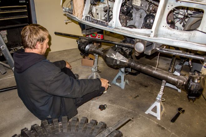
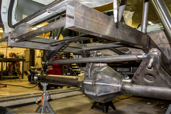
The welds have finally cooled on the custom suspension on our Tracker project (“How to Choose the right Drivetrain"). We went to Jesse Haines Fabrication and asked him to create a lightweight suspension that would be stable on the street while providing plenty of flex on the trail. Haines completely cut off the front and rear frame rails to start with a blank canvas and fabricated new box tube framerails that are narrower to allow for additional tire clearance and suspension packaging.
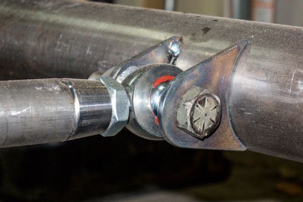
Keeping weight in mind, Haines built the lower suspension links from 1 3/4x0.120-wall chromoly tubing and the upper links from 1 1/2x0.095-wall chromoly. The front and rear lower links are all 34 inches, and we plan to have them heat treated. In its natural form, chromoly is only marginally stronger than 1020 DOM tubing, but heat treating increases the strength of chromoly tubing by 44 percent. All of the links are fitted with top-of-the-line XM chromoly rod ends, jam nuts, and threaded bungs from Rod End Supply. In addition to being chromoly, the XM rod ends use Rod End Supply’s proprietary Nylafiber matrix race that is self-lubricating, decreasing wear and noise and increasing the life of the rod end. The improved strength of Rod End Supply’s chromoly rod ends allowed us to run 7/8-inch shank, 3/4-inch bore rod ends on the lower suspension links and 3/4-inch shank, 5/8-inch bore rod ends on the upper links. A 7/8-inch chromoly XM rod end is comparable in strength to a 1 1/4-inch mild steel rod end but saves a pound and a half each. With four suspension links on each axle and two joints per link, the weight adds up quickly.
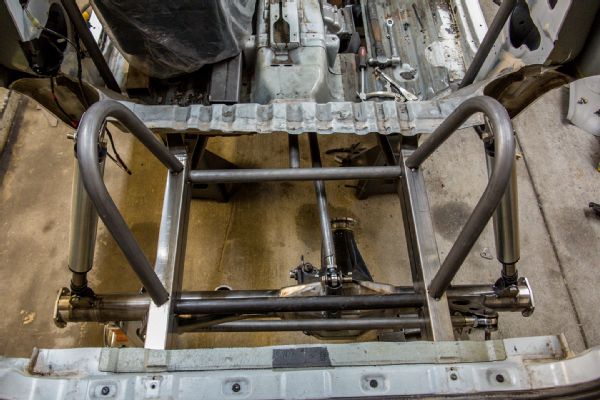
Haines built three-link configurations with a single upper link and a track bar at each end of our Tracker. Some have expressed concern about inconsistent handling with both track bars mounted on the frame on the driver side and the axle on the passenger side, but Haines has built many championship-winning buggies with this suspension configuration in the past. Haines feels that the track bar angle plays a large role in how the suspension performs, and both of our track bars are completely horizontal at ride height. While we do not currently have a sway bar on the Tracker, there is space to package a track bar in the rear and we will report back in the future on whether that is necessary.
Note that information pertaining to the steering in this installment as well, since it is intertwined with the suspension. Haines noted that if we were building a dedicated off-road vehicle, it would be easier to package fully hydraulic steering with a double-ended ram, but we made some compromises in order to retain street manners.
From the factory, our Tracker had an 86-inch wheelbase and a track width of 67 inches. Now it sits on a 101-inch wheelbase with a track width of 74. The belly sits at only 18 inches for excellent stability, yet the suspension provides 4 inches of uptravel so it can still travel at speeds above a crawl without bottoming out over the slightest irregularity.
The front suspension uses a three-link configuration with a track bar. The lower links locate the axle, the upper link keeps the front axle from rotating, and the track bar locates it side-to-side. With a parallel track bar and draglink, this configuration provides plenty of articulation with very few compromises.
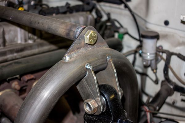
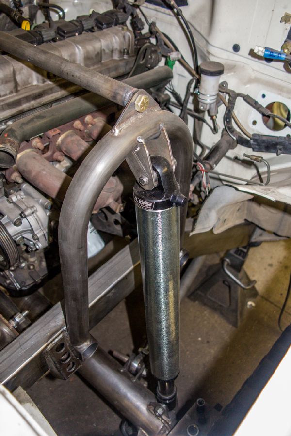
The front shock hoops were constructed from 1 1/2x0.095-wall DOM tubing and tie together with a simple 1-inch crossover tube for strength and rigidity. No need for tube clamps, Jesse Haines Fabrication simply put a threaded bung in each end to make the tube removable to access the engine.
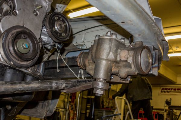
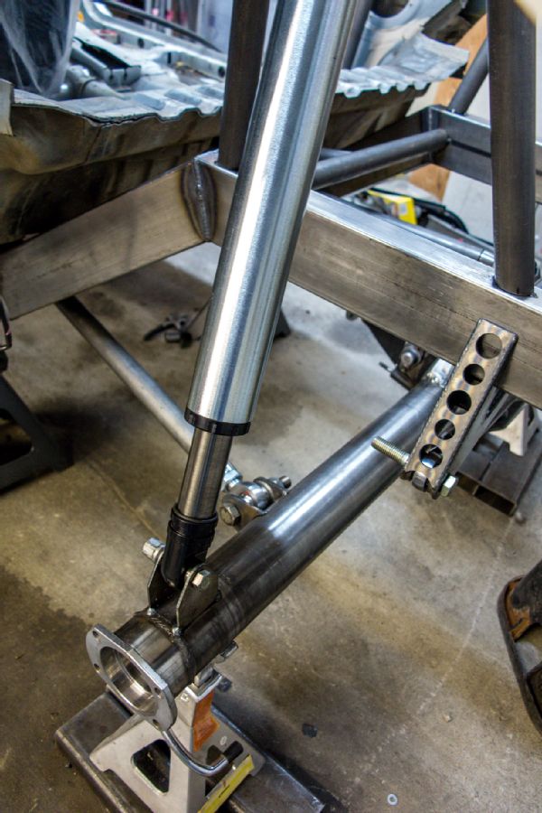
Our original plan involved using a Toyota steering box outside of the frame. This created packaging issues with the track bar bracket, and the tire rubbed the steering box at full lock. A Saginaw box from a Jeep Wagoneer was instead mounted inside of the framerails. The stock steering rack and crossmember weighed 45 pounds; the new Saginaw box weighs 28 1/2 pounds.
The track bar and draglink are completely parallel and nearly flat at ride height. Haines previously fabricated front framerails that are higher and narrower than the stock frame, allowing for 4 inches of uptravel from the ADS air shocks with a relatively low ride height.
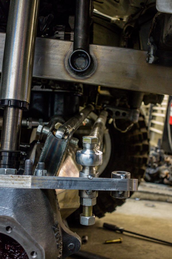
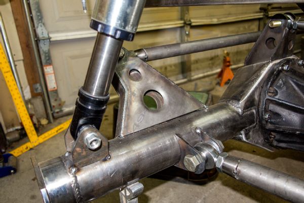
The Hellfire Fabrication steering arms provide various tie-rod and draglink mounting configurations. We ended up with the tie rod mounted below the draglink and under the steering arm in the rear mounting hole. Note that stacking steering components like this can only be done with spherical rod ends, not traditional tapered tie-rod ends.
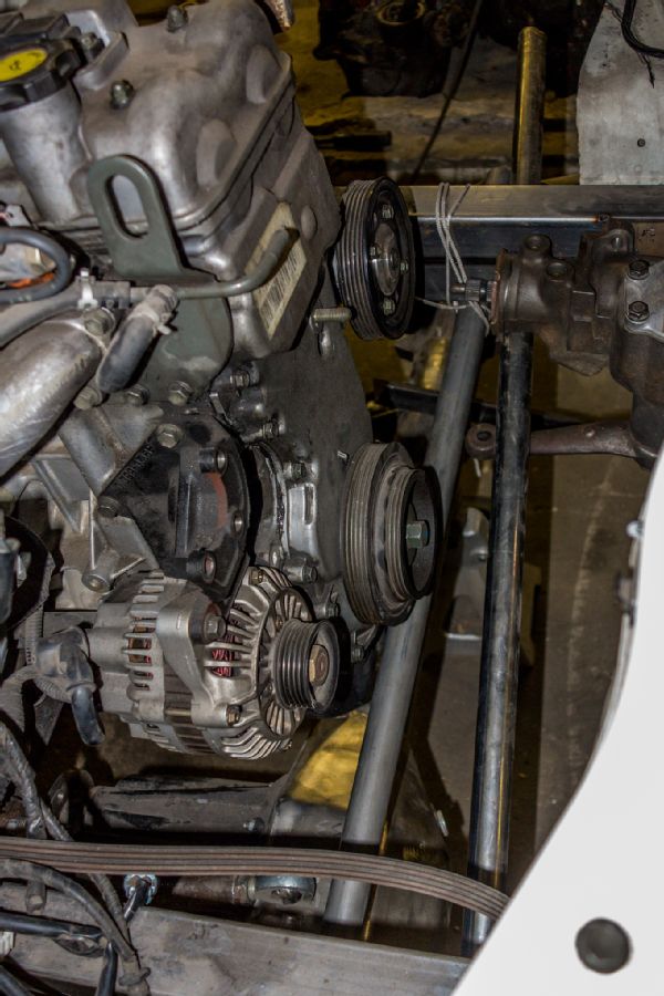
Moving the front axle forward 9 inches created some challenges. Looking down into the engine bay, you can see how the track bar runs right under the crank pulley, with the draglink in front of it. The front differential barely clears the oil pan at full compression, but we did not need to modify the pan.
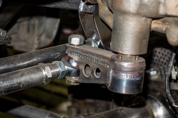
Haines fabricated this trick double sheer steering arm since we are using Rod End Supply chromoly rod ends and high-misalignment spacers rather that tapered tie-rod ends for our tie rod and draglink. The draglink uses 3/4-inch Rod End Supply chromoly XM rod ends and 1 1/4x0.120-wall chromoly tubing.
We sourced all of the rod ends, jam nuts, and threaded bungs for our Tracker project from Rod End Supply. RES has products for every application and budget imaginable. We used the company’s XM line of chromoly rod ends with Nylafiber self-lubricating inserts. If you already know the length of your control arms, RES will even send you fully welded links constructed from DOM or chromoly that are ready to bolt in.
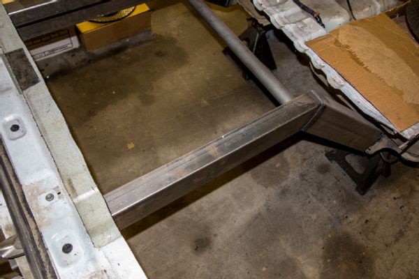
While it was possible to cut the factory bracketry off the stock frame, Haines found it easier to just remove the framerails and construct new ones out of 2x4, 0.083-wall box tubing. The rear sheetmetal went away when the fenders were cut, but we plan to have CR Fabrication build new panels in a future installment of our Tracker project.
Simple tubular shock mounts were built for the rear pair of ADS air shocks. Note how the shocks are mounted as wide as possible to increase stability. The air shocks are tilted in at ride height. Haines explained that this positions the shock perpendicular to the axle at full extension, not over center where the spring rate becomes digressive.
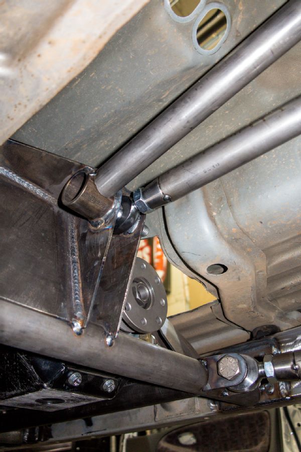
The rear suspension, like the front, uses a three-link with a track bar. The upper mount sees a tremendous amount of rotational force, so Haines tied this piece into multiple crossmembers. The offset Samurai transfer case from Trail Tough allows the upper link to be centered in the chassis.
We are using 2 1/2-inch-diameter, 12-inch-travel ADS air shocks at each corner. These shocks only weigh 14 pounds each and are quite compact, but if you want more control over spring rates, ADS also has a full line of coilover shocks that offer a lot of features for the price.
Some people have expressed concern about having the track bars at both ends of the Tracker mounted to the chassis on the driver side and the axle on the passenger side. Jesse Haines Fabrication has built numerous competition rockcrawlers in this way without issue. Haines explained that the key is to build brackets that place the track bar flat at ride height to prevent a jacking effect.
The lower links sit in the center of the axletube to maximize ground clearance. Putting the links in the center of the tube requires a taller bracket for the upper link in order to get the vertical separation necessary to prevent the axle from rotating under acceleration and braking.
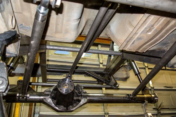
The lower links are mounted inside of the frame so there is no contact at full compression. The links are 34 inches long, which Haines feels is long enough for ample articulation without being so long that they compromise strength and ground clearance. The lower links are also the same length front and rear to minimize the need for spare parts.
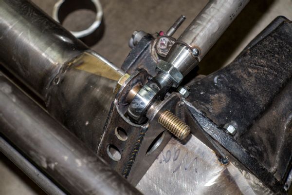
While we used misalignment spacers from Rod End Supply on the draglink, the rest of the company’s spherical rod ends were used in conjunction with weld washers on the bracketry. These washers allow increased movement without the need to reduce the size of the hardware used, such as a misalignment spacer requires.
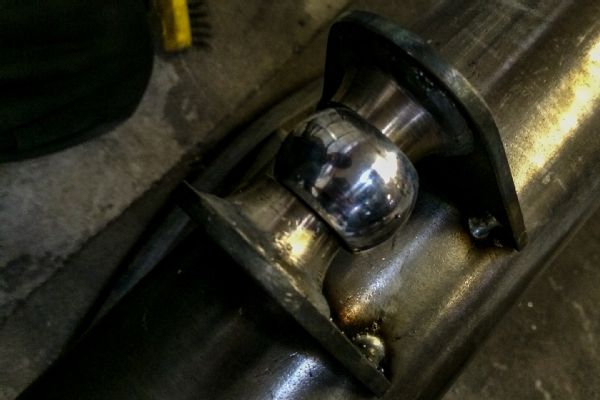
One trick Haines showed us was to use the ball out of an old rod end for fitment during welding. Welding the inside of the mounts first will pull them together, then welding outside will spread the bracket to its desired width.
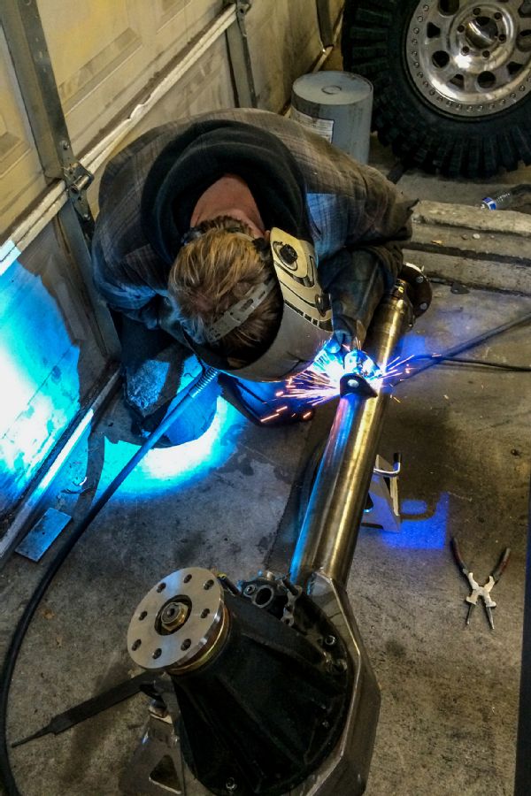
Once the suspension was cycled and all of the mounting was decided, Haines final-welded all of the bracketry in place. Prior to that the brackets were only tack-welded for mockup, in case any changes were necessary.