 Fred Williams
Brand Manager, Petersen’s 4Wheel & Off Road
Fred Williams
Brand Manager, Petersen’s 4Wheel & Off Road
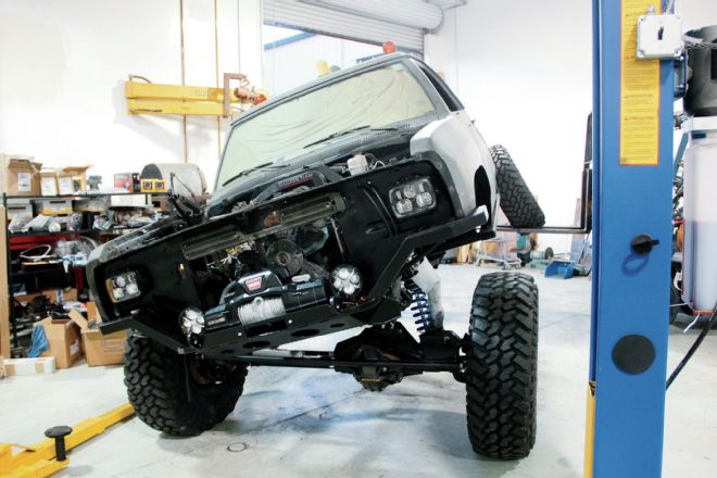
Our Ultimate Tug-Truck is a big anvil of a truck, heavy and tough, but that doesn’t mean it can’t be nimble like a rugby player who can tiptoe and twist down the pitch avoiding the opposing team and leaping to score a try. (Sorry, folks, we threw in some imported ball sports talk. Let us translate. Basically we’re building this big Cummins-powered Dodge to be fast like a running back, strong like a lineman, flexible like a pair of yoga pants, and as simple as the water boy!) Tug-Truck has been getting transformed at Pacific Fabrication in Gilroy, California, and this month we’ll show you the custom suspension destined to earn its keep rolling down the highway and flexing up the trails we find on the UA.
Start any link suspension build with the axle at full compression
This is the truck that we are building to be the quarterback in our upcoming Ultimate Adventure trip. Every year we build something different to showcase the sponsors and ideals of UA, and this year we started with a ’90 Dodge two-wheel drive that had been used as an airplane tug by the military. We tore it down, stretched the frame, dropped a military trailer box on the back, and swung some big axles underneath to deal with 40-inch rubber and 5.9 liters of Cummins diesel torque. Our build plan has changed slightly over the course (as often happens), but as we type up this installment we are literally weeks from the start of the trip and slinging wrenches faster than Bruce Lee wields nunchucks to get this big truck to the trail.
Want to see more of the UA build and how the truck did on the trail? An episode of Dirt Every Day will showcase the truck build, airing on YouTube November 13, 2014. Then the first week of December we will be airing the Ultimate Adventure week of wheeling on the Motor Trend channel on YouTube.
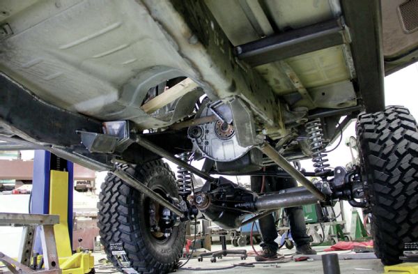
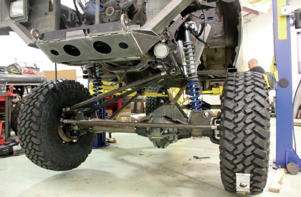
Our front axle is a Dynatrac ProRock 80 with 4.56 gears and a Detroit locker. We decided on a three-link front suspension with a track bar. We need a very strong upper link mount, so Jason Howerton designed an upper axle truss that would tie into the mounting holes that are machined into the cast housing but would also weld to the axletubes. This design helps tie all parts of the axlehousing together.
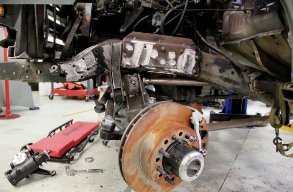
The truss was made to have a single upper link that would clear the driver-side motor mount at full suspension compression. The truss and the frame side track bar mount are all made of 1⁄4-inch plate. It is a good idea to start any link suspension build with the axle mocked up at full compression because this ensures that there will be clearance when the suspension bottoms out when you are, say, coming off a jump or landing from a big drop-off.
On the frame end of the front links the lower link mounts attach to the bottom of the framerails. The lower links are made of 2-inch-diameter tubing, measure just shy of 42 inches, and use BDS forged Flex Joints. The upper link is 411⁄2 inches long and uses rod ends from EMF Rod Ends and 3⁄4-inch bolts. The Flex Joint is rebuildable, and we had the ball machined out to accept a 5⁄8-inch bolt up from the standard 9⁄16-inch. The custom frame mounts were all double-plated for additional strength and abuse and attach to the frame approximately at the same location as the front driveshaft output on the transfer case.
BDS offers a massive adjustable front track bar for late-model Ram heavy-duty pickups, so we had one sent to use on our Tug-Truck. The link has a slight bend to clear the differential cover, and is solid material with a threaded adjuster for centering the axle. It should be plenty strong for our trail rig, and it has enough length to keep the axle from moving far laterally through its cycle of motion.
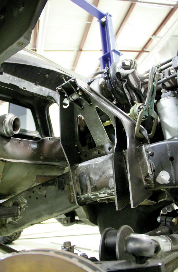
The computer-designed upper shock mounts are made of 1⁄4-inch steel plate that has been plasma cut and then bent and welded. This process allows quick and easy changes to be made should bracket or geometry issues arise during fabrication. The brackets wrap around three sides of the frame and will have a crossover bracket to tie both towers together.
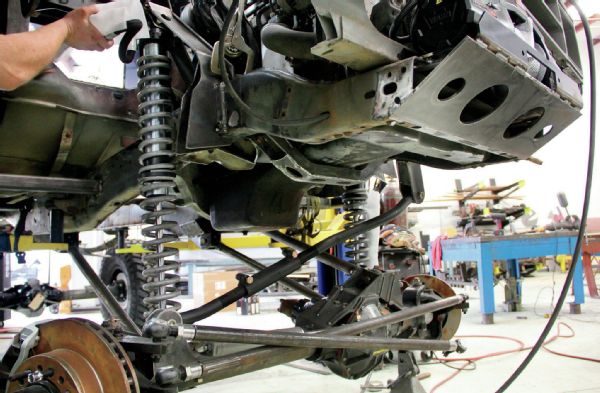
We ordered a set of Fox Racing Performance 21⁄2-inch coilover shocks for the front of the truck. Coilover shocks allow easy mounting and will be strong enough to support the heavy truck with proper coil spring rates. The Performance series shocks from Fox have a remote reservoir, and we went with a 14-inch-travel front shock to allow the truck plenty of flex. We will determine final front spring rate once we have the entire truck built so we know how much weight the springs must support.
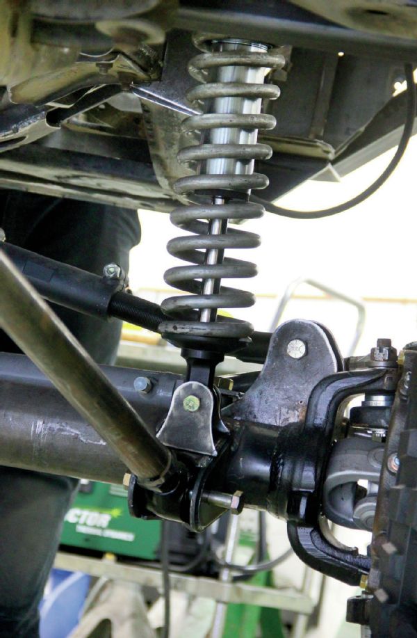
The front lower shock mounts attach just above the lower link mounts on the axle. All suspension mounts are only tacked in place to start in case anything needs to be moved. During the process of building the suspension we constantly cycle and flex the front axle up and down to see if there will be any problems, binding, or interference. A lot of times you need to be sure the shocks don’t swing into the frame under articulation.
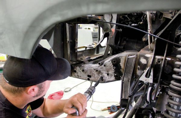
On the driver’s side the PSC steering box was moved forward to allow clearance between the draglink and track bar, but both are on the same angle and plane. The draglink will be slightly longer than the track bar as it runs to the passenger-side steering knuckle where the track link stops shorter at the axle mount, which could cause an ever so slight amount of bumpsteer, but we feel it will be minor.
Kevin Stearns of Pac Fab drilled out new mounting holes and sleaved them to securely move the steering box forward. The inside the of the frame was boxed from front to rear to deter against frame flex, leaving all the articulation up to the suspension.

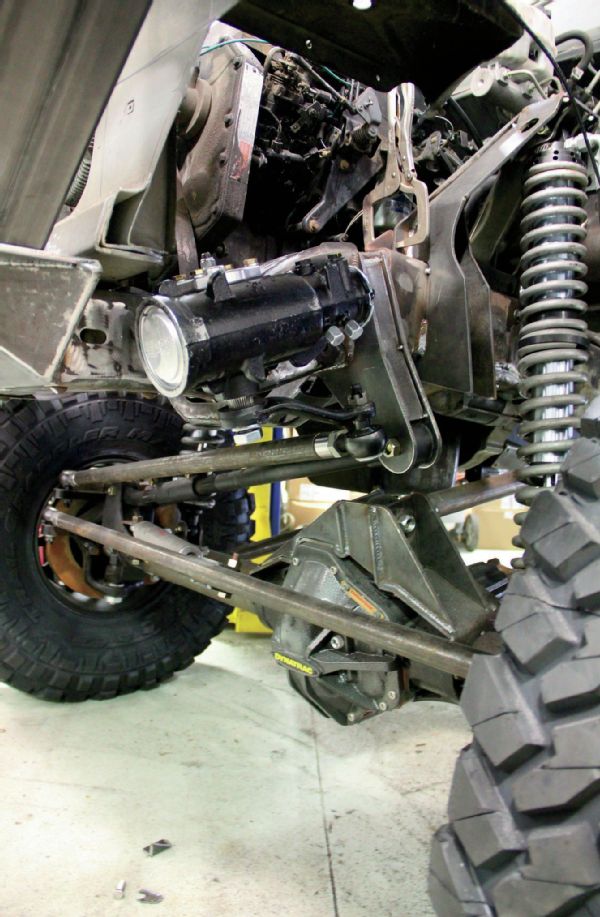
At ride height we are expecting the front suspension to run about 5 or 6 inches of up travel. The front steering links are tucked up high above the centerline of the axletube and use massive EMF tie-rod ends.
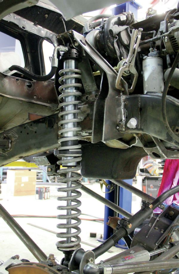
The front suspension at full droop of the front 14-inch shocks offers tons of axle movement but only slight side to side shift with the long track bar. The Fox air bumpstops will mount to the front of the shock tower and land on the raised section of axletube truss at full compression. The custom bumper is made of a Warn universal winch tray and rectangular tubing to tie in with the design of the rock sliders and rear bumper.
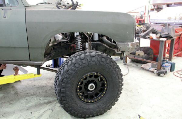
Our Front fenders will not work with our Method Beadlock wheels wrapped with big 40-inch Nittos under articulation and steering. We chose to cut back the rock sliders 3 inches and buzz out a larger wheel opening. We had plans to cut and section the old fenders with a set of new fenders from LMC Truck to retain the body line, then it dawned on us that we may well be smashing these fenders into trees and rocks during the trip, so we are saving the LMC fenders to replace whatever carnage we encounter during the UA.
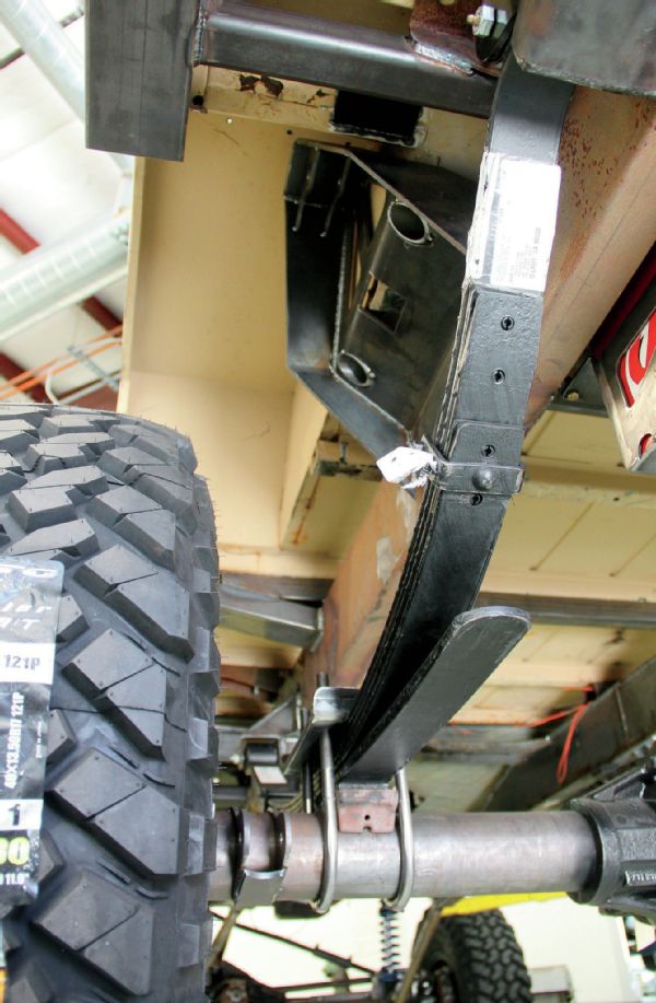
Our rear suspension uses a set of 6-inch BDS leaf springs for a Chevy truck and more custom shock towers, but we’ll have to dive into that more next month.