 Fred Williams
Brand Manager, Petersen’s 4Wheel & Off Road
Fred Williams
Brand Manager, Petersen’s 4Wheel & Off Road
Last month we started an in-depth look at the benefits and detriments of a four-link suspension. We touched on how a four-link will reduce the number of variables down to just the spring rate and shock valving. In addition, a four-link is expensive to do right, and this second installment will hopefully take you from the drawing board to the garage floor.
There are many different link configuration possibilities, but for this discussion we'll stick to a basic four-link where the upper two links start at the frame and converge at the top center of the rear axle. The lower two links will also run from the frame to the outer ends of the axletubes. A three-link is similar, but the upper links are replaced by an A-arm with a single joint at the top of the axle. The three-link setup puts that upper axle joint under greater side loads than the upper two links of a four-link, but it is a viable alternative. Also, suspension builders will argue till the cows come home about what works best, but what we have done is discuss with some of the top desert-race suspension builders how to get you started on a four-link. This design is just a launching pad, and you will need to spend a fair bit of time dialing everything in.
In addition there are many excellent books available to learn more about suspension design. We would recommend:
Chassis Engineering by Herb Adams
Fundamentals of Vehicle Dynamics by Thomas D. Gillespie
Race Car Vehicle Dynamics by Milliken and Milliken.
Though some of these books are pretty heavy, they do help explain the theories behind four-link suspensions, but mostly when applied to street cars and not off-road vehicles. To truly explain a four-link, we would need this entire magazine and a few engineering degrees, and even then there would be things that would be missed. This, however, should be enough to get you started. Just take your time and enjoy the process, because if you don't have the patience to adjust and rebuild your suspension until it works just right, then you should stick to leaf springs.
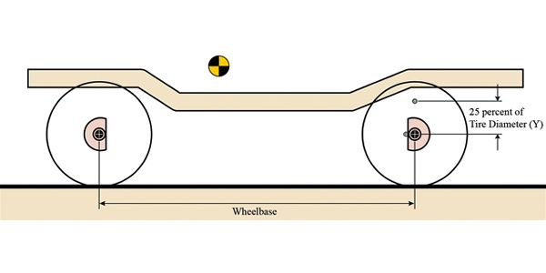 Figure 1
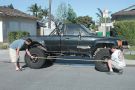
The first step in building a four-link involves a tape measure and some graph paper. What you are going to do is figure out the angle of the links and their mounting locations. This will in turn give you an idea of where to start building your four-link. From there you can fine-tune it. Park the truck on flat ground and measure your wheelbase and the tire size you will be running. Plot the axle centerline points on the bottom half of the graph paper as if you were looking at the side of the truck. Now draw the framerail as it sits above the axle centerlines. This should be where you expect the frame to sit above the axle if you have not yet lifted it. If you know the height and location of your center of gravity of the sprung weight, plot that as well. If not, estimate it by measuring from the top center bolt of the bellhousing to the ground. You may need to add the height of the expected lift if the truck is still stock.
Figure 2
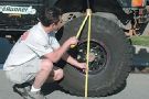
Now plot a point on the front center of the rear axletube. This will be your lower link mount. Some people mount this above or below the axletube, but we have found that the important part is more the difference in height from the upper-link mount. If your truck is going to be very tall, you may want to put these links on the top of the axletube. To find the upper-link axle-mount point, multiply the tire diameter by 0.25 (25 percent). Use that number as the distance in inches that the upper link will be above the lower link at the axle. If you were running 36-inch tires, you would want the upper links to be mounted 9 inches above the lower-link mount. You will most likely be mounting the links 8 to 11 inches apart. The farther apart you can get them right now, the better, as this will help control the leverage of the tires and fight axlewrap. The limiting factor will most likely be the bed of the truck. Continue by plotting the upper- and lower-link axle-mount points. If this is getting confusing, then you are normal; if it's clear as a bell, you may be a bit too smart for your own good.
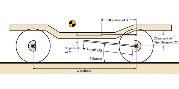 Figure 3
Since you have a rough idea of where your axle-mounting points will be, it's time to move onto the frame mounts. The first point to plot is the lower-link frame mount. To determine this, draw a link with a 5 to 10 degree angle up from the axle mount to the frame in the sideview drawing. Watch where the link intersects with the frame; this point will most likely be near the transfer-case rear output. It should also be as high as possible for ground clearance, but low on the frame to keep the link as level as possible. If you cannot get the link to intersect the frame at 5 to 10 degrees, you may need to move the lower-link axle mount up on the axletube. If so, you will also need to move the upper-link axle mount as well to keep the predetermined 8- to 11-inch vertical spacing between the links at the axle.
Another option is to consider building a crossmember mount below the framerails. At this point you should be realizing that a four-link involves tons of variables and compromises, and we haven't even gotten to actually looking under the truck yet! Now take the horizontal distance from the lower-link frame mount to the lower-link axle mount and multiply that number by 0.7 (70 percent). This is a good horizontal length of the upper links. The distance apart that you mount the upper and lower links on the frame should be about half the vertical distance apart of the link's axle mounts. Again, try to keep the links as level as possible.
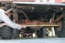
Start looking at the width of the frame at the point where the upper links attach, and write this measurement down. Subsequently measure the distance along the axletube from just shy of one brake mounting plate to the other. This will be the distance apart of your lower-link axle-mounting points. If at this point you are starting to really like the idea of leaf springs, then we congratulate you for having some common sense. If you are still thinking that you'll be the talk of the town with your new super four-link suspension, then dig out that piece of graph paper and sharpen your pencil, because there is more work to do.
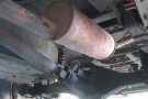
If you have a pile of graph paper crumpled into balls and a headache from thinking too hard, then you are right on track. The tricky part comes when you take your drawing and see if you can actually attach the links you drew on the truck's frame and axles. This is where compromise comes in. You may need to move the fuel tank, exhaust, or various other low-hanging parts of your truck. There is always a bit of adjustment available. The upper links can be slightly longer or shorter than 0.7 (70 percent) of the lower links, but try not to pass 0.6 (60 percent) or 0.8 (80 percent).
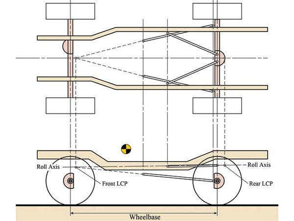 Figure 4
On the graph paper draw lines up to the top of the paper from the front- and rear-axle centerline, upper- and lower-link axle, and frame-mounting points. Next, in the upper space draw the rear axle from the top view with the lower-link axle mounts plotted at the distance apart you measured from the actual rear axle. Follow that by drawing in the framerails from the top view with the center of the frame over the center of the rear axle. But wait, there's more.
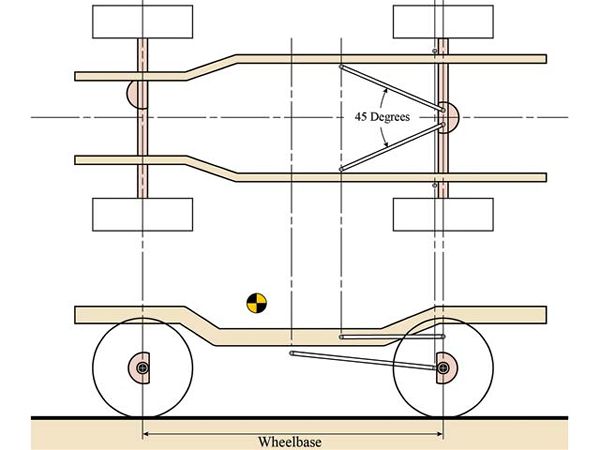 Figure 5
Draw in the upper links first. Remember to have them start from the frame, but at the axle keep them slightly separate to allow access to the nuts that will go on the ends of the bolts running through your rod ends. Now grab an angle finder. It is very important that the angle of the two upper links be no less than 40 degrees. This angle is what locates the axle laterally or side to side. The smaller or more shallow the angle, the weaker the lateral control. This again may mean shortening the upper links, but try not to make them less than 70 percent of the horizontal length of the lower links. If need be, you may need to shorten the lower link's horizontal length as well, but try to keep them as long and as level as possible. If you are wondering when you get to start installing your really cool new coilover shocks, then you might need a lesson in patience. Get another cup of java and keep studying.
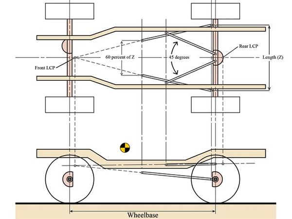 Figure 6
To reduce the rear steer of the axle, we need the tire to move towards the center of the frame, side to side, as it articulates and not towards the center of the frame, front to back. First you need to draw in lines extending from the links until they converge when viewed from the top of the vehicle. These convergence points are known as the lateral constraint points (LCP). The upper-link's extended lines will most likely converge at a LCP just behind the rear axle. The lower-link's extended lines should converge at a LCP somewhere forward of the transmission, depending on how much of an angle you give them when looking at the top view. An angled set of lower links helps the upper links locate the axle laterally and fight rear steer, but also requires a larger area to slide over obstacles. The best route seems to be a slight angle, but not at severe as the upper links. An acceptable angle will have the lower link's separation at the frame equal to 50 to 70 percent of axle-mount separation, which may require fabricating a crossmember to mount them to, as discussed earlier.
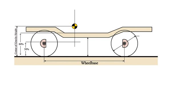 Figure 7
Moving on, take your center of gravity height measurement and multiply it by 0.5 (50 percent) and write down your answer. Now multiply the height by 0.8 (80 percent) and write that down. Next, draw a vertical line through the front axle perpendicular to the ground, and plot two points using your answers above as the number of inches from the ground. The space between these two points represents the percent of antisquat you will be aiming for. This will be discussed further in Figure 9.
Figure 8
Next draw a vertical line down from the LCPs to the sideview drawing. Extend lines from the upper links back and lower links forward until they cross the lines you brought down from the LCPs. This will show you the heights of the LCPs. Now when you connect the two LCPs on the lower drawing with a straight line, you will get the roll axis. This is the imaginary line perpendicular to which the axle will articulate. As such, you want the front of the roll axis slightly lower than the rear. This will give better handling and less rear oversteer as the axle articulates. If your roll axis leans toward the back of the truck, you may need to lower the upper link's frame mount or increase the height of the axle bridge. Just don't let the upper link's frame-mounting point get lower than the lower-link's frame-mounting point--better yet, keep them apart. As you can see, there will be many opportunities to adjust and diverge from the original design to get the geometry correct.
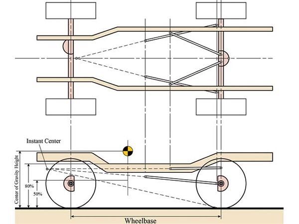 Figure 9
To make sure your suspension transmits power to the ground, you want a certain amount of antisquat. This will let the tires move the vehicle forward without the energy compressing or expanding the suspension. The perfect amount of antisquat is debatable, depending on the driver's desires. Some want the vehicle to crouch when accelerating, but this is sending the power into the springs. Some want the vehicle to lift under acceleration to gain more traction, but this can let the axle walk under the vehicle instead of propelling it forward. We will try to design the suspension not to squat or lift excessively, while erring on the squat side. The way to determine antisquat is to run a line from the contact patch (CP), or center of where the rear tire touches the ground, to a point where the upper and lower links would converge in the front of the vehicle while viewed from the side.
The point towards the front of the vehicle where the links would converge is known as the instant center (IC). The line from the instant center to the contact patch of the rear tire should run across the vertical line through the front tire. If it is within the 50 percent to 80 percent of the center of gravity height at the front tire that we determined in Figure 7, then it should be a good amount of antisquat to start from. If you want it to lift more, you need the line to be closer to the center of gravity or above 80 percent. If you want it to squat more, you want the line closer to the ground or below 50 percent. Now if the antisquat is not where you want it, you must start adjusting the link-mounting points. If you move the lower axle point up on the axle, remember to raise the upper link's axle mount as well. If you move the lower link's frame mount, then you may need to move the upper link's frame mount as well. Then after you think you have gotten the links where you want them, move your new dimensions back to those of Figure 8 and make sure your roll axis is angled towards the front of the truck. Expect to spend many long hours moving your measurements back and forth between Figures 8 and 9 until you have everything dialed in.
PhotosView Slideshow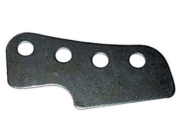
When you get to the upper link's frame mount, we recommend using a bracket that has multiple holes drilled for attaching the upper links such as this one from A&A Manufacturing. Attach this bracket so you can move the upper link's frame mounts up and down from the ground. This will be your initial point of adjustment to fine-tune the suspension whether you are going racing or rockcrawling.
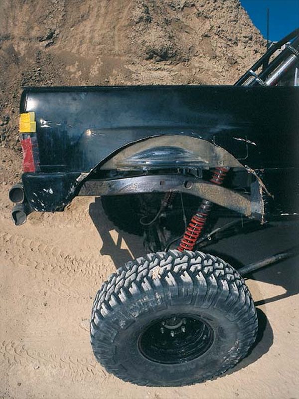
Now that you have everything in place, it is time to cycle the suspension. Notice if the axle moves straight up and down as it should or if it swings forward as it articulates, as it shouldn't. Are the links and rod ends binding? If so, do the brackets need to be angled to follow the line of the links? Plus, what about everything under the truck--exhaust, fuel tank, spare tire, and so on? Is there clearance for these or do they need to be moved? If everything seems to be right, it's time to burn in the welds. Just remember that it is not uncommon to need to tear into the suspension again to get it to work a bit better. Do not be surprised if you are adjusting things three or four times before you get it how you like it. You may still want to change more, depending on the terrain you encounter or the driving style you prefer. This is only one way to build a four-link, and different builders will try different methods. If you enjoy a challenge and are willing to spend the time, money, and energy to fine-tune your suspension, then a four-link may be right for you. If not, then stick to a professional kit, or leaf springs, and just go have fun on the trail.
Four-Link Suspension Tech - Part 1