Disc Brakes, Brake Installation, and Ford Bronco - 4-Wheel and Off-Road

Disc Brake Installation - Stop It Down Alan Huber Art Director Photographers: Cody Huber

Like a mom always reminding her kids to brush their teeth or wash behind their ears, someone is always chastising wheelers about the safety of their rigs. We don't like hearing it, yet we know it's a good idea. Although as wheelers we may take additional chances with our 4x4s off-road, we don't want our vehicles to be the cause of any harm to others through poor engineering, right? Right! You've made Mom proud.

131 0507 Ssb 01 Z Photo 9092920

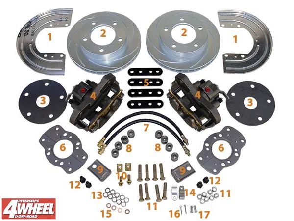
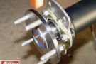
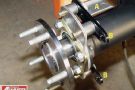
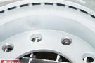
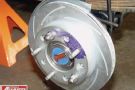
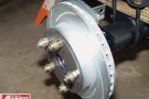
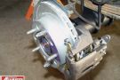
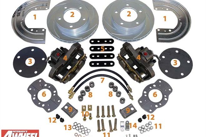
Here's what's in the A118 kit: (1) Dust shields, (2) rotors (slotting and zinc-plating are optional), (3) wheel spacers, (4) cast-iron calipers with integral parking brakes, (5) caliper mounting brackets, (6) adapter brackets, (7) brake hoses, (8) mounting spacers, (9) parking-brake cable brackets, (10) banjo bolts and blocks, (11) mounting-bracket bolts and nuts, (12) caliper mounting bolts, (13) reducing rings, (14) parking-brake cable clevis, (15) crush washers, (16) cotter keys, and (17) clevis pins.

One of the most mundane, yet important, areas of safety is the brakes. If you're now running around on tires as tall as some cars, the trickle-down effect takes over. The big tires are probably double (or more!) the weight of the originals. Stronger axles to handle those big tires also add weight. The suspension lift to fit those tires affects weight transfer by raising the truck's center of gravity. And then there's the performance hit created by the added leverage of tall tires. Factory brakes get overwhelmed.

The drum brakes used on many OEM vehicles are simple and satisfactory for stock trucks, but if you're building a high-performance 4x4, then don't forget high-performance brakes. Stainless Steel Brake Corporation. (SSBC) has all sorts of rear disc-brake conversion kits to fit virtually any 4x4's rear axle. We ordered one for a 9-inch Ford truck axle (PN A118), but many of these steps are similar to other SSBC kits. If you aren't comfortable working at home on a system as important as brakes, a reputable shop can easily handle the install for you.

PhotosView Slideshow After removing the wheel and drum, disconnect the brake line (using a line wrench) and plug the end to keep brake fluid from draining out. Unbolt the axle retainer, slide out the axleshaft, disconnect the parking-brake cable, and remove the backing plate. The axleshaft and its retainer can then be slid back into place, but don't bolt it down just yet. The SSBC kit includes two-piece adapter brackets that are marked and must be oriented properly. Slip the two halves of the SSBC adapter bracket around the axleshaft between the retainer and axlehousing end and tighten (40 lb-ft) using the original axle-retainer bolts. Next, using the eight (four per side) tubular spacers, caliper mounting brackets, and 7/16x2 Grade 8 bolts, mount them to the adapter bracket as shown. Be sure to add the parking-brake cable bracket to the bolt that is on top and toward the front of the vehicle (A). Note how the third hole in each of the caliper mounting brackets faces toward the rear of the vehicle (B). Slide the dust shield over the bracket bolts, add the locking nuts, and torque everything down to 70 lb-ft. Be sure the parking-brake cable bracket (arrow) is rotated to a facing-forward position as you tighten the bracket bolt. Here's were we ran into a small stumbling block. The SSBC rotor is meant to be centered on the lug studs (lug-centric) instead of the axle hub (hub-centric). The kit includes these small reducing rings to slip over the studs and in turn center the rotor. This all works fine as long as the reducing rings fit flush against the axle flange--and ours didn't. The studs on our axle had a shoulder that held the rings about 1/16-inch out causing them to also stick out of the rotor. This means the wheel would never sit flush when mounted, leaving the rotor loose. Our options for making the reducing rings work included machining them to a shorter length or reaming them to a larger inside diameter--neither of which seemed to be an optimum solution to us. We also thought if we ever needed to change a tire in sand or mud, we wouldn't want five tiny rings to worry about dropping once the wheel was off. (Lug nuts alone are hard enough to keep track of!) We decided a quick trip to the machine shop to get the rotor redrilled seemed a better solution. The new holes were laid out and drilled for a snug fit on the studs and were also slightly chamfered on the backside to clear the stud shoulders. The rotors (11.75x0.875 inches) could now be slipped over the studs and centered themselves beautifully. SSBC sent us vented rotors that are not only zinc-plated for a corrosion-resistant finish, but are also slotted to relieve the gases that occur when brakes are heated during stops. This achieves the same goal as cross-drilled rotors without the cracking that can sometimes happen. Slotting also leaves fewer holes to get filled with mud. Some applications may need to run this spacer for backside wheel clearance. The SSBC kit is made to work with 15-inch-diameter and larger factory steel wheels, so some aftermarket rims may not clear the caliper. Those will need to run the spacer. Our wheels cleared fine without the spacer. The cast-iron caliper (with 54mm piston) slips over the rotor and is held in place by two M12-1.75x25 Grade 10.9 bolts coated with locking compound. Depending on the particular spacing requirements, the caliper may need to be shimmed slightly so the outer pad does not drag on the rotor. Ours took a couple of washers (arrow) to gain about 1/32-inch pad-to-rotor clearance. The SSBC caliper comes assembled with parking brakes. Route your original e-brake cable through the SSBC bracket and clip it in place. The end of the cable attaches to a clevis and pin which are retained by a cotter key. You'll need to change the brake lines slightly when going to rear discs from drums. Disc-brake calipers are floating and need a flex line so that as pads wear the line can extend. Our stock Ford rear brake line ran to a central point on the chassis and a single flex line dropped to a T-fitting, which then had hard lines out to the drum wheel cylinders. The rigid lines needed to be cut back and reflared, and short flex lines run to the calipers. The SSBC hoses were too long for our purposes, yet would've worked beautifully if they went straight to a frame-mounted bracket as on a car. We purchased two 8-inch hoses (NAPA PN 25159) pre-crimped with banjo fittings on one end and 3/8-inch inverted flares on the other. A simple hose-to-hard-line bracket and clip solidly held the lines in place. The last step is to remove the residual pressure valve from the master cylinder. This valve holds a small amount of pressure in the line as needed by drum brakes. This pressure is detrimental to pad life with disc brakes and so must be defeated. Disconnect the rear brake line running from the brake port (fed by the smaller of the two reservoirs) and thread an extractor or No. 6 sheetmetal screw into the brass seat. Being careful not to deform the brass, pull it from the cavity to gain access to the valve. Remove the small rubber flapper valve and reinstall the brass seat. Tap the brass seat into the proper position and bleed the master cylinder before reinstalling. Finally, bleed the rest of the brake system by starting at the wheel farthest from the master cylinder (right rear) and working toward the closest (left front). Approximately 40 pumps of the brake pedal will bring the inboard (moveable) pad to within 1/32 inch of the rotor for proper clearance. Carefully drive the vehicle and check for correct brake function and a firm pedal.

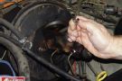
The SSBC kit is designed to work with the vehicle's stock proportioning valve arrangement, but you may want to fine tune your front-to-rear brake bias by adding an aftermarket adjustable proportioning valve. Brakes stop best when adjusted so the front wheels lock up a fraction of a second before the rears. There are many brands and styles of adjustable valves to choose from, but all are installed in the rear brake line and reduce the amount of fluid pressure going to the rear brakes. Many late-model vehicles have a combination valve that handles rear brake proportioning along with several other brake functions such as serving as a mounting point for warning light switches, bleeder valves, and metering valves and serving as junction blocks. Combination valves must be modified before using an aftermarket adjustable valve. We modified a late '70s Ford combination valve for this story. Other makes may look the same, but function differently, so get a repair or service manual to figure out how yours operates and what needs to be changed.

131 0507 Ssb 14 Z Photo 9093061

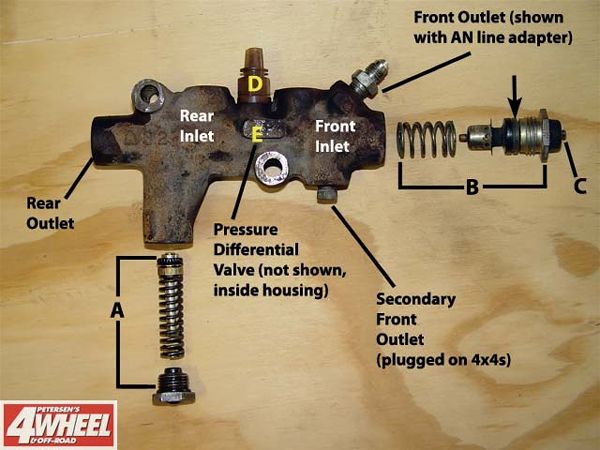
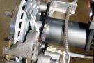
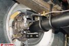
A- Proportioning Valve: Reduces fluid pressure to rear brakes
B- Metering Valve: Holds off pressure to front discs until slower rear drums can react
C- Bleeder Rod: Must be pulled out when bleeding factory brakes
D- Brake Light Warning Switch
E- Pressure Differential Valve: Senses pressure imbalance

Here is a combination valve out of a late-'70s Ford with the major parts labeled. If you're adding an aftermarket adjustable proportioning valve along with rear disc brakes, the factory valve must be modified as outlined here. The factory proportioning valve (A) must be gutted by removing its internal spring. There is also a metering valve at the front (B) that balances disc/drum system actuation by holding off pressure to the front discs until the rear drums catch up. Remove the small washer (arrow) near the middle of the valve to disable it. From the factory, the bleeder rod (C) must be held out by a special clip when bleeding the system. This will no longer be necessary once the metering valve has been modified. Many people may want to ditch the entire valve, which is fine, but then the brake warning light switch (D) will no longer operate unless it is relocated. Note also how the combination valve serves as a handy junction block for the four brake lines. The pressure differential valve (E) senses any hydraulic pressure imbalances between the front and rear brakes and alerts the driver with the brake warning light. This valve is not modified, but be sure to mount adjustable proportioning valves downstream of this valve or your warning light will stay on permanently.