Solid rivets look cool. They lend an air of vintage race car or aviation inspiration to a project. They also enable dissimilar metals to be joined, or, in the case of the hood on our project vehicle here, allow an aluminum blister to be attached to an aluminum hood with no need for welding.
However, installing solid rivets by hand can be awkward, often requiring two people, one to hold the bucking bar (in a manner not unlike a body working dolly, behind the workpiece) and another to hammer against the rivet setting tool, or, depending on your installation method preference, one to mushroom the end of the rivet by hammering, while another holds the setting tool in position.
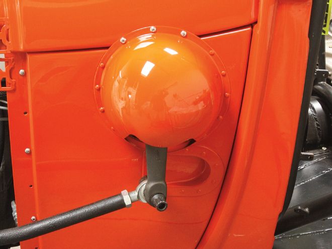
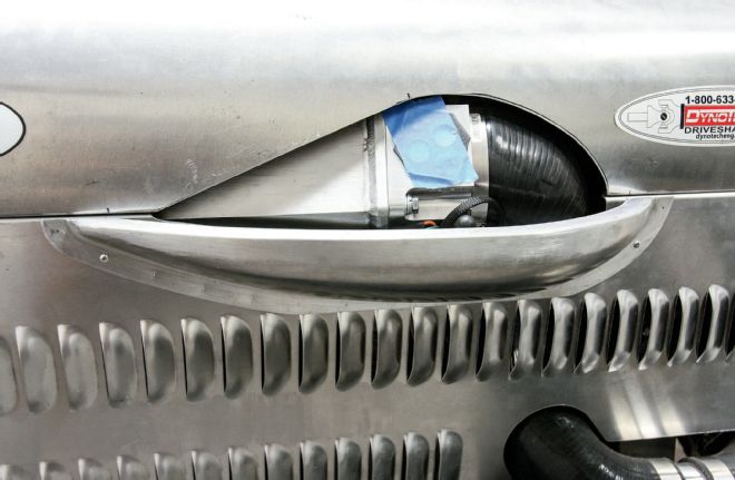
1. Despite mounting the Borgeson late-’60s Mopar steering box as far out as practically possible, the curved nature of the Model A cowl meant that on full righthand lock, the Pitman arm was close to the bodywork, and the bolt and heim joint fouled it. A recess was temporarily cut into the cowl side to accommodate full travel.
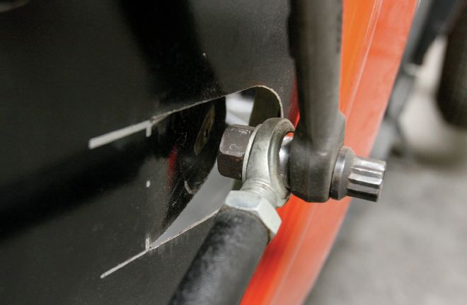
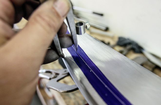
2. Being a dry lakes car, the Model A has steering stops preventing full travel of the steering box. The blue tape denotes the maximum left and right travel.
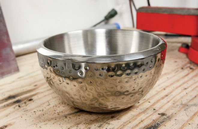
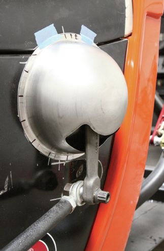
3. Making sheetmetal blisters is fun, but time-consuming, so a little out-of-the-box thinking can yield similar results. This stainless steel bowl was spotted in a housewares store for under $10. Ignore the outer skin, the important part is that the inner skin is concave throughout, unlike similar single-skinned bowls that will have a flat bottom, which is no good to us.
4. Cutting the outer skin away and using a hammer and dolly to flatten the lip we have a perfect blister. With the Pitman arm removed, the blister was placed over the steering shaft and the blue tape lines transferred using fine line tape. The smaller hole shown was cut for this, but we realized that the hole for the Pitman arm would have to be cut at an angle, as the cowl is angled compared to the travel of the arm. At this point we decided to enlarge the hole to allow full travel with the steering stops removed, should this ever be required.
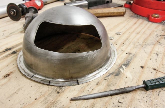
5. The hole was cut out using Rotabroach cutters and a cut-off wheel, followed by a little dressing with a file. The lip was shaped to match the curve of the cowl panel it will be riveted to.
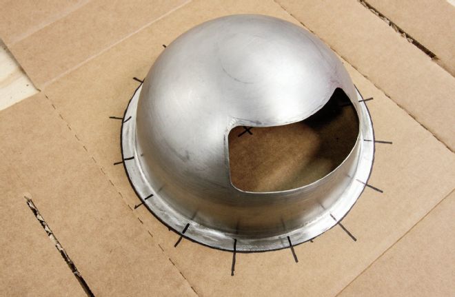
6. Wanting the rivets to be spaced equidistant from each other, a template was drawn on cardboard, and the blister placed on top of it to mark where the lip should be drilled.
7. Double-checking the drill marks don’t interfere with the gap between the cowl side and top panel. The cowl side panel was then removed.
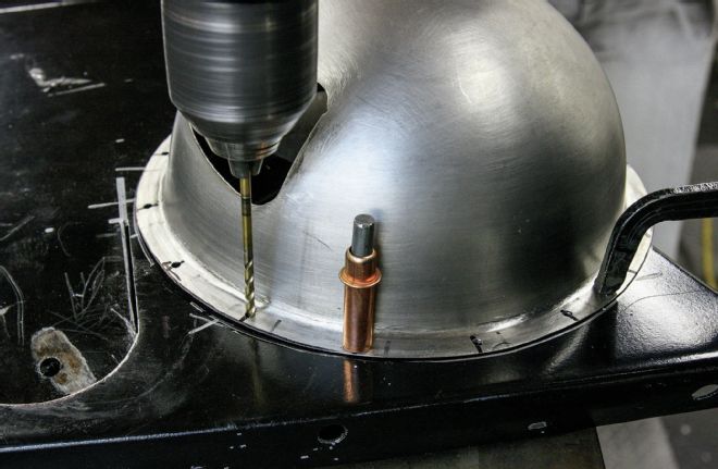
8. With the blister clamped in position, the holes were drilled through both pieces of sheetmetal at the same time. Clecos were also used to align the panels once the first couple of holes were drilled.
9. An airsaw was used to remove some of the cowl side panel that will be behind the blister, to facilitate installation. Now the Pitman arm has to be installed before the panel is mounted, some extra “wiggle room” was needed for clearance.
10. At the same time as the blister, we also fabricated a recessed panel to tidy up the area we’d cut to allow the Pitman arm to move through full travel. This was made from three separate pieces, the curves cut freehand using our trusty Miller 375 X-TREME plasma cutter.
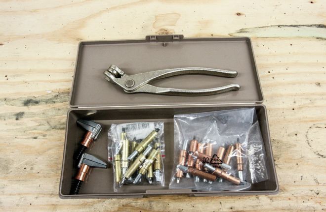
The Eastwood Company has made the process several steps easier, with the introduction of its new Solid Rivet Kit. This kit contains not just a pneumatic rivet gun, 1/4 pound each of 1/8- and 3/16-inch rivets, a bucking bar, as well as rivet sets for both sizes of rivet, but also 1/8- and 3/16-inch Clecos and a pair of side clamps, to hold the work in position while riveting. That pneumatic gun isn’t a repurposed air hammer either, but a dedicated gun that should be run at 45 psi, specifically for the purpose of riveting.
Obviously you’ll require an air compressor to use the kit, but we’d say the hardest part of the whole exercise is planning the rivet placement and spacing the holes equidistant from each other, especially round the perimeter of an oval blister. The instructions supplied with the kit offer some good advice on spacing, for both single and double rows of rivets, as well as staggered double rows. This is more critical for joints where strength is a concern, unlike our examples here.
11. Here’s how the panel fitted, prior to trimming and welding it together.
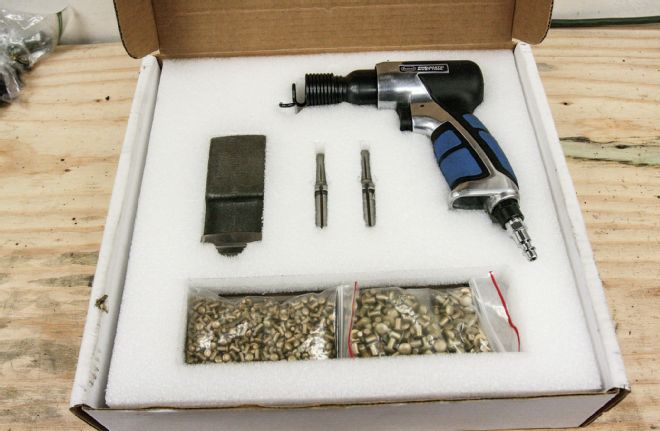
12. Here’s the Eastwood Solid Rivet Kit, shown here in prototype packaging as it’s a brand-new product. It includes the pneumatic rivet gun (not a repurposed air hammer), 1/8- and 3/16-inch rivets, a bucking bar, as well as rivet sets for both sizes of rivet.
13. Also included in the kit, packaged under the rivets, are 1/8- and 3/16-inch Clecos and a Cleco tool.
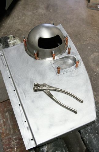
14. Once the recess was fabricated and welded, and all parts stripped to bare metal, everything was Cleco’d together and checked for fit.
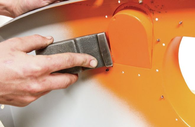
15. We then shot some primer and body color on the cowl panel and the backside of the blister and recess, to prevent rust forming between the panels, and re-installed the Clecos.
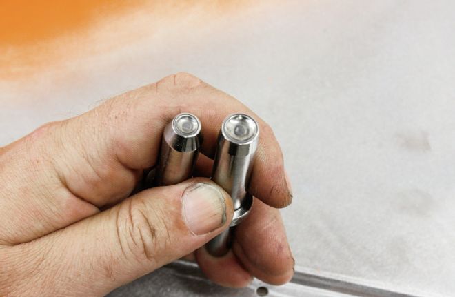
16. Here are the two different sized rivet sets, for 1/8- and 3/16-inch rivets.
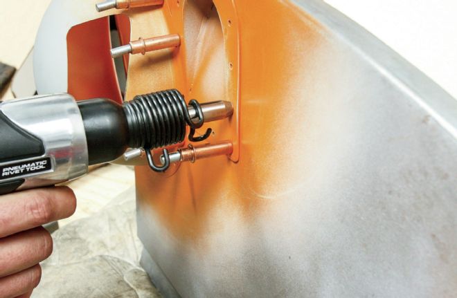
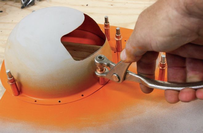
17. With the rivet set in the gun, it was placed over the head of a rivet placed in the hole …
… while the bucking bar was held firmly against the back side of the rivet.
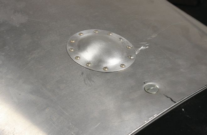
18. We’d suggest practicing on some scrap metal first, rather than on your work piece as we did, but after a little practice the back side of the rivets should look like this, uniformly flat with no warpage to the surrounding sheetmetal.
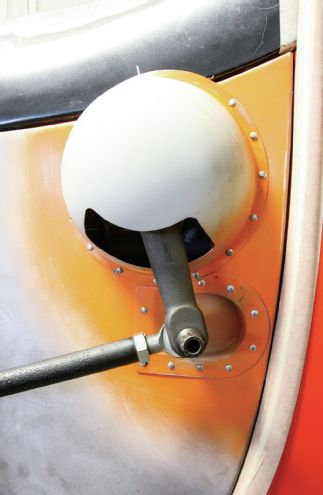
19. With all the rivets in place, our panel looked like this. Back on the car we double-checked it for fit, and that the blister cleared the steering shaft. We used three 10-32 stainless Allen bolts to bolt the top of the blister to the cowl top, allowing each panel to be removable.
20. We also needed a small blister at the front of our hood to allow clearance for the air intake tubing. After annealing the aluminum to make it more workable, we used an Eastwood sandbag and mallet to form a blister.
We borrowed a prototype kit from Eastwood to undertake a couple of tasks on the ex-Rod & Custom lakes racer project car, and will definitely be getting our grubby mitts on a production kit, as not only do the rivets provide a strong joint and look good, but the process is actually fun, when not all garage tasks are! We’re sure we can find numerous applications without thinking too hard. We used the kit to attach a steel recess to allow our Pitman arm clearance on the cowl, to attach a stainless steel blister to the cowl, and to attach a couple of aluminum blisters to our hood.
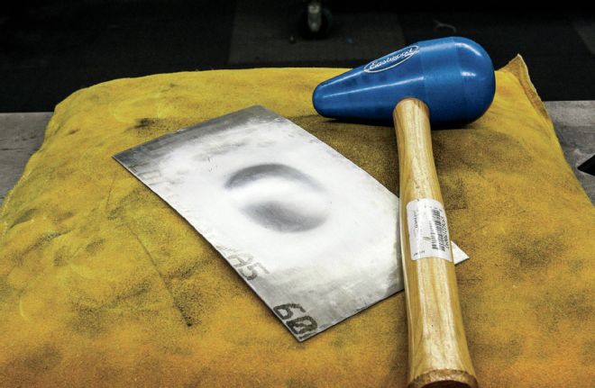
21. After a few minutes we had a symmetrical blister, tall enough to clear our underhood tubing.
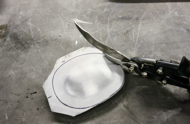
22. Tin snips made light work of trimming the edge of the blister to provide a mounting flange.
23. Again we set the rivets an equal distance apart before setting the blister in place, not forgetting to cut a hole in the hood first!
24. Here’s what happens if you let the rivet set drift off-center while using the pneumatic gun. Take care and take your time.
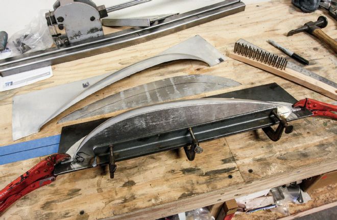
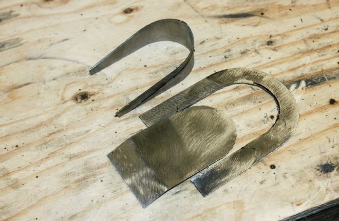
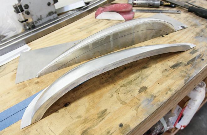
25. Our hood required a blister to clear the intake. This meant half the blister would be on the top and the other half on the side. We sourced an 18x6x3-inch aluminum Speed Blister from Mooneyes and cut it in half using a bandsaw. We then cut aluminum to close off each half of the blister, fabricating a jig to hold everything in place while welding.
26. Once welded and sanded smooth, we used a compass to scribe a line 3/4 inch from the edge of the closing panels, along which we cut, to form a return lip.
27. Forming the return lip this way resulted in less warpage during welding, and made clamping the panels in the jig a lot easier.
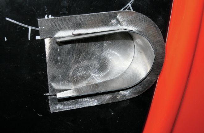
28. We did have to trim the lip on the lower half to clear the louvers. Planning ahead when laying out the louvers would have prevented this!
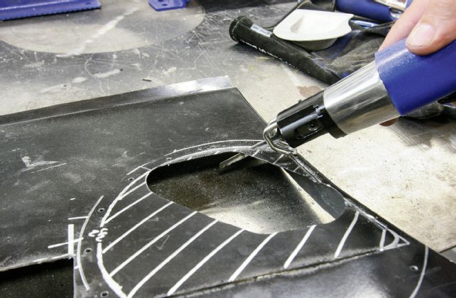
29. While the lower half of the blister fit flush against the hood side, the upper section required some work to align the lip with the curved hood top. We split the blister as shown, and welded a section into the resulting gap.
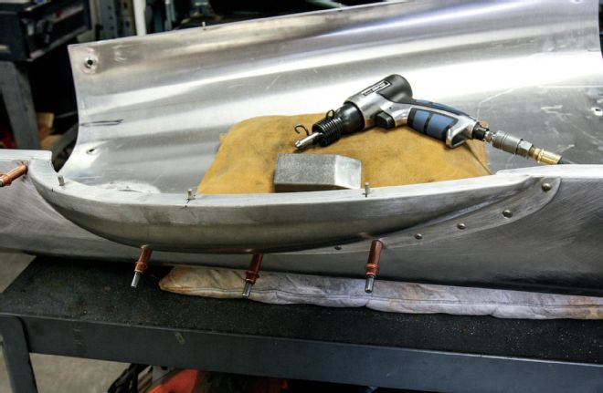
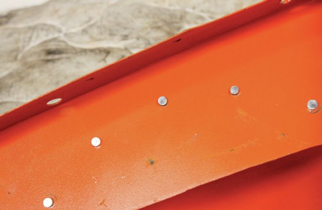
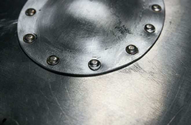
30. Again, we used the rivet gun to attach the blister halves to the hood. The hood top was placed on an old pillow, and a sandbag used to weigh it down to prevent it from moving while we riveted the blister in place. Note the pins (actually aluminum rivets) which locate the hood top on the sides (arrow).
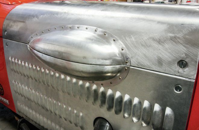
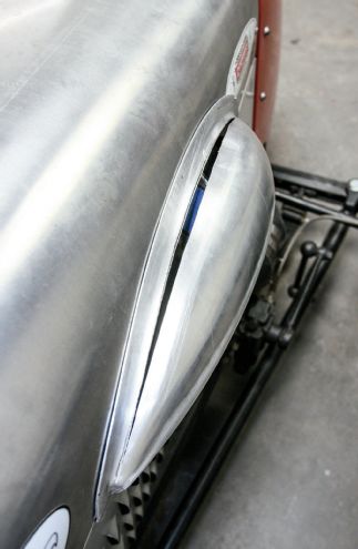
31. Riveting complete, here’s how the blister looks on the car.