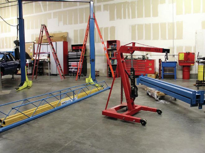
Pulling an engine and transmission out of a race car can be a taxing project when you're using old technology like your basic cherry picker. Enter: Shop Crane. These guys build awesome systems for professional racers, Saturday-night short trackers, and do-it-yourselfers alike and you can install it yourself right in your own shop or garage.
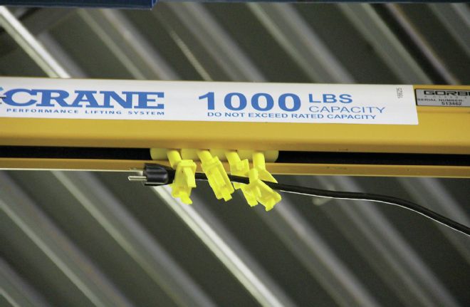
Tim Loughlin of Shop Crane recently visited Circle Track's headquarters in Tampa, Florida, to help us install our very own dual-bridge 12-foot system which will make it safer, easier, and much faster for us to pull engines, unload heavy parts, and even pull bodies from chassis. Our system consists of two hoists each rated at 1,100 pounds—giving us the ability to lift pretty much anything you could find in a racing environment.
We installed our Shop Crane around our two-post lift, which is a common application according to Loughlin, who also told us that the systems are available in 8-, 10-, and 12-foot standard sizes but can be built to custom specifications as well. The entire process took somewhere in the ballpark of 3 to 3.5 hours with three people performing the installation.
While the system includes all of the necessary hardware, you'll need a few ladders and handtools to complete the installation, as well as a hammer drill to create holes so that you can anchor the system into your concrete floor. Hammer drills aren't usually a staple in most shops, so keep in mind many hardware stores rent them for a low daily rate.
Shop Crane systems are extremely versatile and can be customized to fit almost any application. They start at $2,400. The 12-foot high two bridge electronically controlled system we're installing retails for $4,222.
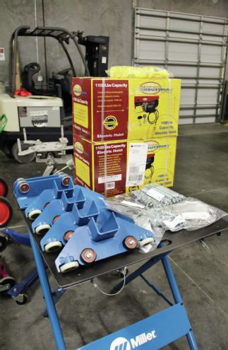
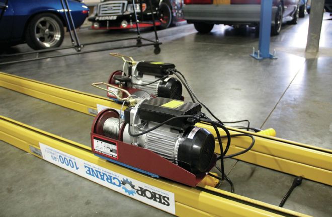
01. In addition to four posts, two runways, and two bridges our Shop Crane comes complete with all of the hardware needed for installation along with the hoists and trolleys which you see here.
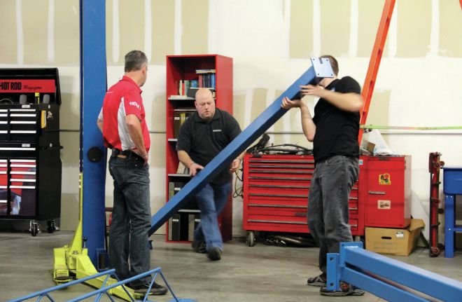
02. First, Loughlin, Editor Rob Fisher, and Source Interlink Media Shop Manager Darrell Kunda, picked a starting point for our first column from which all of the measurements will originate. We knew that our system had to straddle the pre-existing lift, froming a rectangle. In our case, the cross-dimensional length of that rectangle needs to be 21815/16 inches. This is one of the most critical measurements of the Shop Crane system.
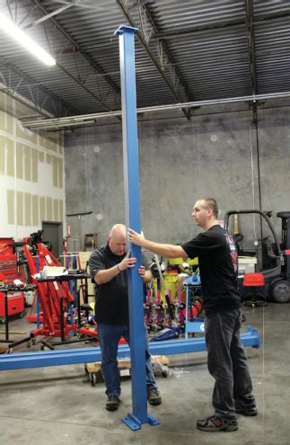
03. Before we get down to the cross measurements, we used rough estimation and placed the second, third, and fourth columns in their approximate spots, knowing that they had to be roughly 12 feet wide center to center and 15 feet long center to center.
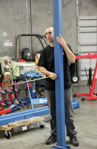
04. Next, we measured the distance from the first column to the second and adjusted it’s placement, continuing around the perimeter of our rectangle to provide closer measurements.
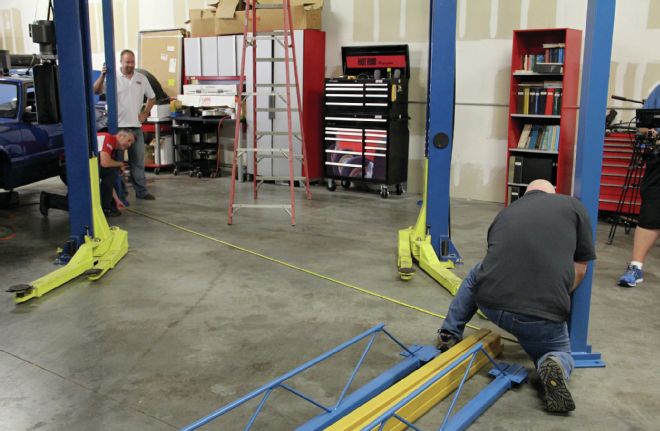
05. With our perimeter in place, we cross-dimensioned to ensure a perfect rectangle. Making sure that the diagonal measurements are completely equal is a vital step to ensure that your Shop Crane system will be structurally sound and function properly when the installation is complete.
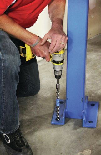
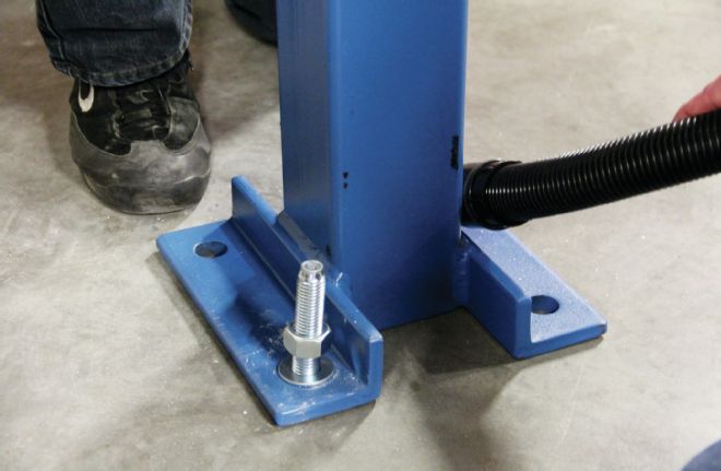
06. After we double checked to make sure that our measurements were sound, Fisher used a hammer drill with a 3/4-inch bit to drill four 4-inch deep holes to anchor the first column into the concrete. Notice the blue painter’s tape placed exactly 4 inches from the tip of the bit to make it easy to measure the depth of the hole. We also had a vacuum on hand to clean up the concrete dust.
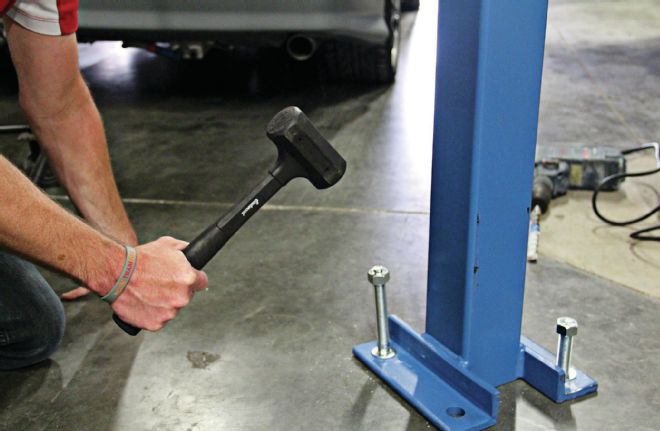
07. Using a hammer, Fisher drove the anchors into the holes before spinnig the bolts on loosely. We needed to be sure there was play in the column so that the rest of our installation would go smoothly. The bolts get tightened later once the runways are in place.
07. Using a hammer, Fisher drove the anchors into the holes before spinnig the bolts on loosely. We needed to be sure there was play in the column so that the rest of our installation would go smoothly. The bolts get tightened later once the runways are in place.
08. We re-measured yet again and used a Sharpie to mark where the remaining 12 holes needed to be drilled. This is a helpful step that we added so that our measurements would be exact in the case that a column shifted accidently. It is also important to be sure that the tabs at the top of the columns are aligned facing each other lengthwise so that the runways will lock into their tabs.
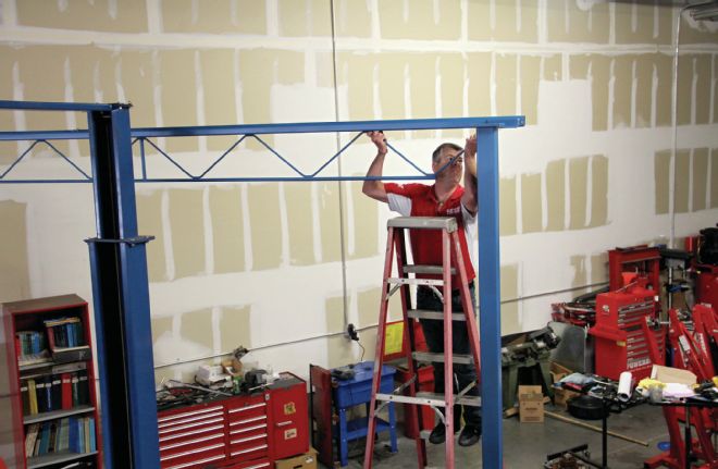
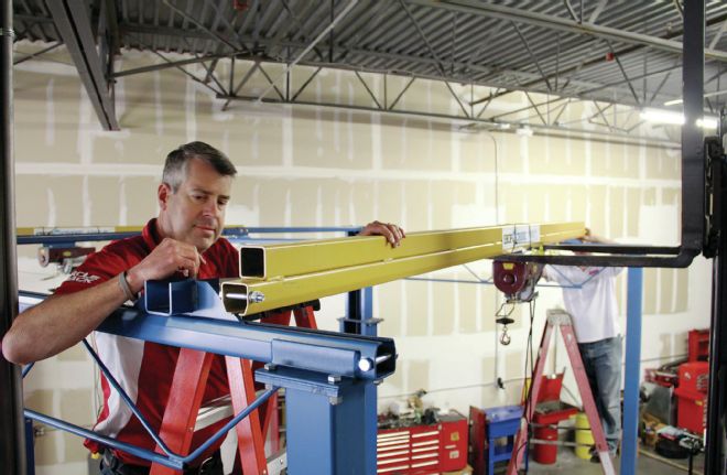
09. After drilling and anchoring the three remaining columns, both runways were carried up to the top of their respective columns running lengthwise and placed over the columns, locking into the tabs. The runways will support the bridges, which move back and forth from the front to the back of the vehicle, and are home to the hoists.
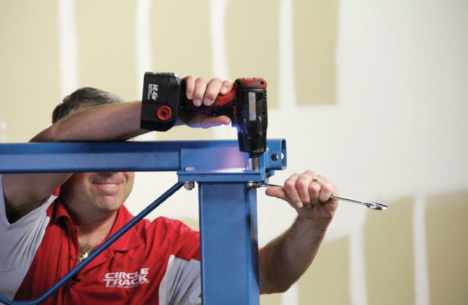
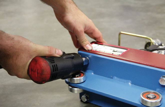
10. Four bolts were dropped through the holes at the top of each column, securing the runway to the columns, before each nut was tightened with an impact gun.
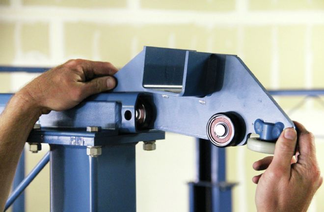
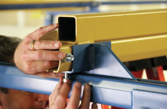
11. The bridges will be secured to these end trucks in the U-shaped slot. Each end truck, which slides into the runway, has four vertical wheels and two horizontal wheels to allow it to move freely. There is no need to grease the tracks, in fact Loughlin recommends against it. Just take an air hose and periodically blow the tracks clean.
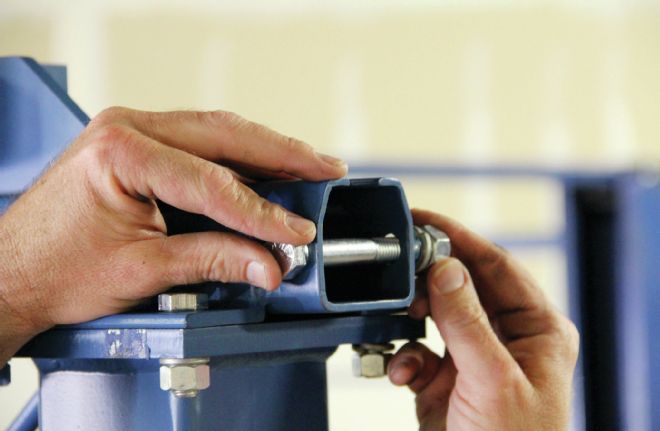
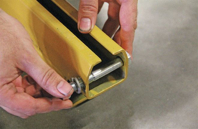
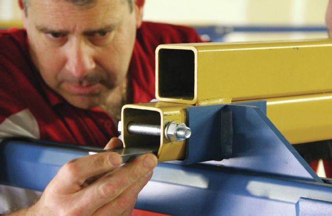
12. A bolt was threaded across the end of each runway’s tracks to keep the end trucks from sliding out and falling onto the ground. Take care not to pinch the tracks by over-tightening these stopper bolts.
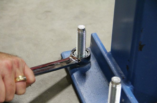
13. Next, we went ahead and tightened the nuts to the anchors at the base of our columns, so that each side of the structure was stiff and secure for the installation of the bridges. Remember to check and retighten the bolts a few weeks after installation. You might choose to cut the anchors after tightening so that they are flush with the bolts, to avoid the risk of tripping.
14. With the structure almost complete, we turned our attention to our hoists and bridges. To prepare the hoists to mount on the bridges, Kunda bolted a trolley onto the top of each hoist. The four-wheeled trolley allows the hoist to move side to side in the bridge.
15. With the bridges turned upside-down, each hoist was slid onto the track. (Note: We used a forklift to lift our bridges up to the top of the structure, since it is 12 feet in the air. Because each bridge weighs approximately 130 pounds and each hoist weighs an additional 40 pounds, you might choose to wait to install the hoist until the bridge is installed at the top of the structure.) Yellow clips were also slipped onto the track to hold the electrical wire up when we’re finished.
16. Stopper bolts were tightened onto the ends of each bridge to lock them into place atop the end trucks and ensure fit and stability once installed.
17. After turning the bridge right-side-up onto the forks of our forklift, we lifted the bridges lengthwise to place them onto the end trucks of either runway. We realize not every shop has a forklift and if yours doesn’t, go ahead and put the bridge up first (with the trolley in its track) and then follow up by attaching the hoist to the trolley once the bridge is in place.
18. Tapped and threaded plates were slipped into the ends of each bridge and bolted down to gap the track so that the ends can’t clamp. This is done just in case there is a slight misalignment in the runways, so that the end trucks will have the ability to float in and out just a little bit while the bridge runs up and down the runway.
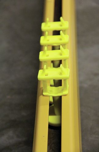
19. With our Shop Crane installation almost completely finished we installed tagline clips to hold the hoists’ electrical wires out of the way, ensuring that they won’t get tangled during use. With the extension cord threaded through the clips, they will space out as the hoist is moved back and forth.
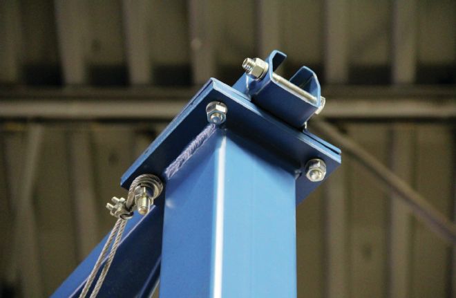
20. To hold up the extension cord, we removed two of the bolts on the inside of the columns on the electric side and installed a cable spanning the length of the runway before retightening the bolts.
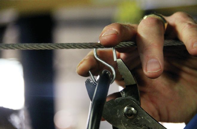
21. S-hooks were hung on the cable and tightened around the extension cord so that they can move freely as the bridges are moved from front to back.
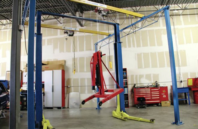
22. The old cherry picker now obsolete, we used our hoist to pick it up to load into the back of our pick-up and send to the scrap yard.
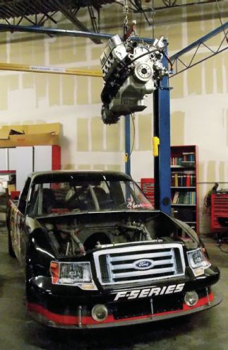
23. With our Shop Crane ready for use, we tested it out by pulling the engine and trans out of our Circle Track truck in mere minutes. The process was easy, quick, and safe and we couldn’t be more impressed with our new system. Want to see it in action? Head over to www.circletrack.com and check out the video.