If you drive your hot rod, even once in a while, then you depend on all of your gauges to be reliable and accurate. Just a small percentage of miscalibration can result in engine damage or failure, overheating, or just running out of gas. Driving around with an incorrect speedometer can be dangerous and could earn you a ticket-not to mention the constant reminder that an important part of your rod or custom just isn't operating the way it should.
We don't know how many of you are driving around out there with inaccurate speedometers, but considering that almost every one of you has probably changed your tire and wheel combination or your rearend gears sometime in the past, it's probably a pretty high percentage.
We take it for granted that a speedometer measures vehicle speed, but technically, the speedometer measures the number of driveshaft revolutions per mile, which is displayed on the gauge face as speed in miles per hour. When you change the tire height or the rearend ratio, you change the ratio between the number of driveshaft rotations during one complete tire rotation, which changes the number of driveshaft revolutions per mile. The speedometer reading has to be corrected to reflect the change. Taller tires will cause the speedometer to indicate too slow a speed, and shorter tires will cause it to indicate too fast. Similarly, taller gears (lower numerically) will have the same effect as taller tires, and the speedometer reading will be slower than actual. In either case, you need to figure out the amount of error in your speedometer and how to correct it.
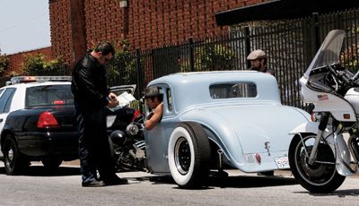
 An inaccurate speedometer can have expensive consequences, as Wil Sakowski explains to Spencer and Nelson from Sakowski Motors. Cop? Who said he was a cop?
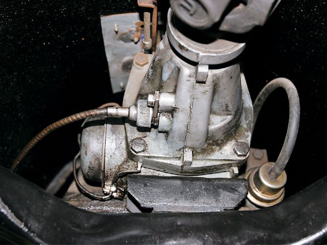
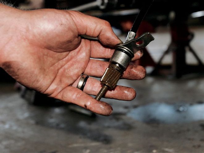
The speedometer cable, which ends at the driven gear, is threaded to the transmission tailhousing, as shown on this GM TH350. It is readily accessible.
The speedometer cable, which ends at the driven gear, is threaded to the transmission tailhousing, as shown on this GM TH350. It is readily accessible.
An inaccurate speedometer can have expensive consequences, as Wil Sakowski explains to Spencer and Nelson from Sakowski Motors. Cop? Who said he was a cop?
An inaccurate speedometer can have expensive consequences, as Wil Sakowski explains to Spencer and Nelson from Sakowski Motors. Cop? Who said he was a cop?
The speedometer cable, which ends at the driven gear, is threaded to the transmission tailhousing, as shown on this GM TH350. It is readily accessible.
The speedometer cable, which ends at the driven gear, is threaded to the transmission tailhousing, as shown on this GM TH350. It is readily accessible.
How Off Are You?
A simple seat-of-the-pants method for figuring out the accuracy of your speedometer is to find an open stretch of highway, preferably one with mile markers. If there are no mile markers, you can measure the distance of one mile with a vehicle that you know has an accurate speedo. Maintaining a constant speed, get a passenger to calculate the time between mile markers using a stopwatch. Divide 3,600 by the elapsed time in seconds that it took to go one mile and that'll give you your actual speed. For example, say you made your one-mile run at a speedometer reading of 60 mph, and your one-mile elapsed time was 50 seconds. Dividing 3,600 by 50 equals your actual speed of 72 mph. You already know that going 72 mph when you think you're going 60 could earn you a speeding ticket.
Dividing the actual speed by the speedometer reading will tell you the percentage of error. In this case, 72 divided by 60 equals 1.20, so the speedometer is reading 20 percent too slow.
As you may have figured, this method, even with all the arithmetic involved, is far from precise. Stopping and starting a stopwatch at exactly the right moment, and maintaining a perfectly constant speed for a mile, is difficult. But this will put you within the margin of error for mechanical speedometers.
 The driven gear extends into the tailhousing.
Mechanical Speedo Calibration
On a typical mechanical speedometer, the gauge is operated by a flexible cable running from the transmission. The transmission output shaft drives the cable via a pair of nylon gears. The drive gear is a worm gear located in the transmission, running off the output shaft. It turns the driven gear, a pinion gear that is connected to the end of the speedometer cable.
Changing the ratio between the drive gear and the driven gear will change the speedometer reading. A driven gear with fewer teeth will speed up the speedometer reading; more teeth will slow down the reading. On the drive gear, it's the opposite-fewer teeth will slow down the reading and more teeth will speed up the reading. Generally, it's easier to change the driven gear at the end of the cable than to dig the drive gear out of the transmission housing.
So going back to the earlier scenario where the speedo is reading 60 mph but your actual speed is 72 mph, the situation can be remedied by swapping the driven gear for one with fewer teeth.
The speedometer cable, which ends at the driven gear, is threaded to the transmission tailhousing, as shown on this GM TH350. It is readily accessible.
The speedometer cable, which ends at the driven gear, is threaded to the transmission tailhousing, as shown on this GM TH350. It is readily accessible.
An inaccurate speedometer can have expensive consequences, as Wil Sakowski explains to Spencer and Nelson from Sakowski Motors. Cop? Who said he was a cop?
An inaccurate speedometer can have expensive consequences, as Wil Sakowski explains to Spencer and Nelson from Sakowski Motors. Cop? Who said he was a cop?
Roger Luckow at Speedometer Service Company gave us some rough estimates of how much driven gear tooth count affects the speedometer on various transmissions. On GM Powerglides, manuals, and some TH350s (depending on the tailhousing length), there is approximately a 5 percent change per tooth. In other words, switching to a driven gear with one more tooth would cause the speedometer to read 5 mph too slow at 100 mph, 3 mph too slow at 60, and so on. On 700-R4s, TH400s, and some TH350s, the change is approximately 3 percent per tooth on the driven gear and 6 percent on the drive gear. The approximation on Fords is approxi-mately 5.25 percent per tooth for driven gears and approximately 10 percent per tooth on the drive gear.
Remember that these are approxi-mations only, since variables such as rearend gear ratio and tire diameter will affect these numbers.
The TCI Web site features the following formula, applicable to GM, Ford, and Chrysler, to help you determine the correct number of drive gear teeth you need based on your drive gear, axle ratio, and tire size:
(Number of drive gear teeth x axle ratio x tire revolutions per mile) divided by 1,001 = the number of teeth needed on the driven gear for accurate speedometer reading.
To determine tire revolution per mile, divide 20,168 by the tire diameter in inches. Most speedometer supply shops can do this calculating for you, if you can tell them the amount of speedometer error, number of teeth on the current driven gear, transmission type, rearend ratio, and rear tire diameter.
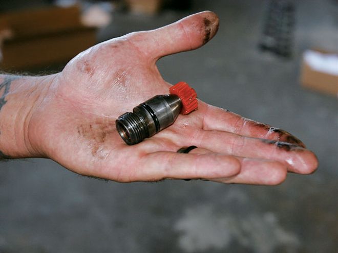
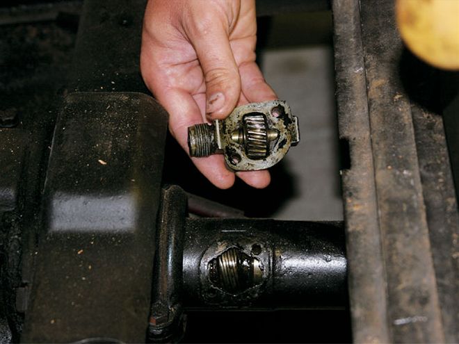
 This driven gear is from a Ford C4 four-speed. The gear is held in place with a small C-clip that must be removed in order to pull off the gear.
Measuring Those Meats
Since we've already managed to make things complicated, let's do the same for measuring tires. Measure tire diameter from the ground to the center of the axle, with the tire fully inflated, and multiply by two. This will give a more real-world measurement since the tire is flattened where it rolls on the pavement.
An even more accurate measure-ment is the rolling circumference- the distance the tire travels in one complete rotation. Roger Luckow suggests putting a chalk mark on the bottom center of the sidewall and on the pavement at that same point. Roll the car forward until the sidewall chalk mark is at bottom center again, and measure that point on the pavement from the starting point. That distance divided by Pi (3.14159265) will give you a precise real-world diameter to use in the above equations.
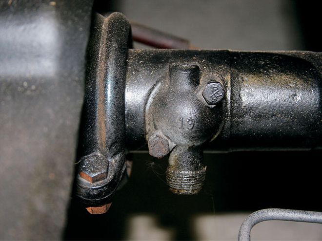 On early Fords with torque tubes, the driven gear is located in this housing, which bolts on with a gasket. The drive gear slides onto the driveshaft inside the tube.
Ratio Adapters
An alternative method of cali-brating a mechanical speedometer is with a ratio adapter. A mechanical ratio adapter is a small gearbox used to increase or decrease the rotation speed of the cable on a mechanical speedometer. Ratio adapters can be installed anywhere in the system, such as inline along the cable, or at the speedometer, but they are typically located at the transmission. Once again, the company from which you buy your ratio adapter will need to know the amount of speedometer error and other info in order to provide you with a properly geared ratio adapter.
Electronic speedometers, although they aren't operated via cables and gears, are also affected by changes in tire size and rearend ratio. Electronic ratio adapters control the number of electronic pulses per mile instead of cable rotations.
Adapters are also available to allow the use of mechanical speedometers with electronic transmissions or electronic speedometers with mechanical transmissions. Abbott Enterprises is one company that offers various products along this line. Its Cable X adapter, for example, picks up a pulse reading from the vehicle speed sensor (VSS) in an electronic trans and converts it into the correct cable rotation speed for your mechanical speedometer.
Electronic Speedometer Calibration
The overall principle of electronic speedos is similar to the mechanical versions. Instead of a pair of gears at the transmission and a cable running to the gauge, a VSS at the transmission is wired to the gauge.
Although the science behind electronic speedometers is more complicated than mechanical versions, calibrating them has been made much simpler, since there are no mechanical components to swap.
The big name instrument companies, including Auto Meter, Stewart Warner, and Classic Instruments, have offered programmable models for years. Once a special feature, push-button calibration is offered in virtually all of their model lines. Electronic speedos can be recalibrated over and over, and the procedure on most instruments is as easy as resetting a clock.
On Auto Meter and Stewart Warner programmable speedometers, the procedures are similar:
Push and hold a button on the gauge face, start the engine, and release the button. Re-press the button at the beginning of a driving course (driving distance varies according the manufacturer, so follow their specific instructions), drive the course, press the button one last time. On Classic Instruments speedometers, the process is as simple as setting a series of 12 dip switches (located on the back of the gauge) to a particular pattern of open and closed positions, specified by calibration charts in the instruction manual.
In all cases, the final step is to drive your car, confident that the speed indicated on your speedometer is the speed you're going.