If you’ve owned a Tri-Five Chevy you’ll know that squeezing a wider wheel under the rear can be problematic, not only because of the low wheel arch lip, but because the leaf springs mount outboard of the chassis ’rails, limiting the width of wheel that will fit. If you want to retain the stock rear quarter-panels, we can’t help with the former, but Classic Performance Products can certainly provide an answer to the latter conundrum.
The company’s complete 1955-57 Chevy Leaf Spring Relocation Kit (PN 5557LSRK-C) comprises dropped leaf springs, tie plates, shackles, upgraded adjustable aluminum shocks, U-bolts, and a weld-in rear shock crossmember. Check CPP’s website for the complete kit or bracket-only kit. The kit lowers the car 1 inch and relocates the springs from outside to under the framerails, the springs drop it a further inch, with additional drop provided by lowering blocks, in this case another 1 inch, for a total of 3 inches.
The tubular shock crossmember allows for correct shock angle alignment and eliminates the upper trunk floor mounting points. It should be noted the complete kit will only work on a wagon if the fuel tank is relocated, and will not work with a rear sway bar. Follow along as CPP installs the kit on the ’55 Revive project.
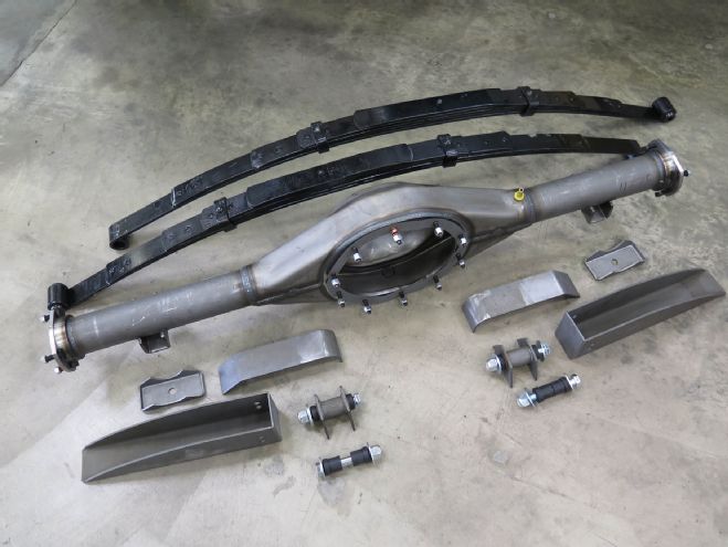 Available as a bracket kit only (everything shown in front of the rearend housing) or a complete kit with lowered springs, the Leaf Spring Relocation Kit lowers a car 1 inch by moving the springs from outside the frame to underneath the frame, with a further 1 inch lowering using the new springs. CPP’s Currie Crate 9-inch (PN GMB5557X-MT-LRK) is specifically built to accompany the kit.
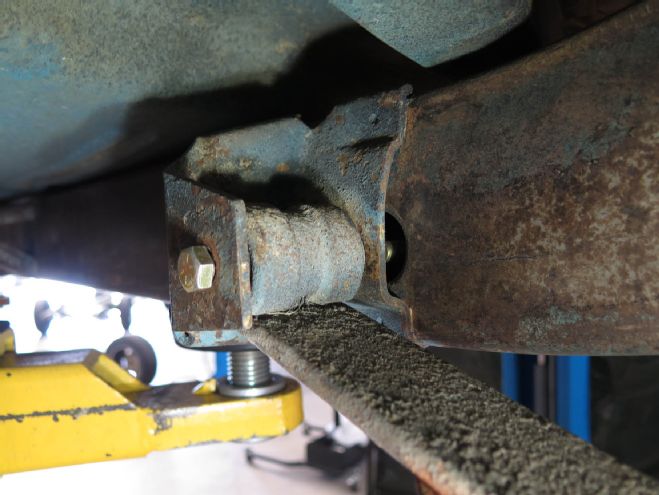
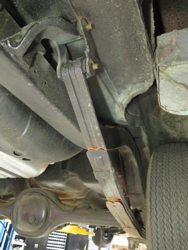 The stock leaf spring and hangers locate outside the framerails, limiting the width of tire usable.
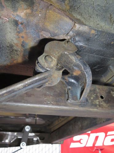 The rear hanger can be removed from the frame once the old shackle is disassembled and removed from the hanger and spring.
 Disassembling the front spring mount is as simple as removing the bolt from the bush in the spring eye.
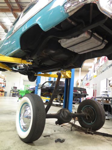 The complete rearend and suspension can now be removed from the frame.
 The spring hanger brackets were removed from the framerails using a Miller Electric Manufacturing Company plasma cutter.
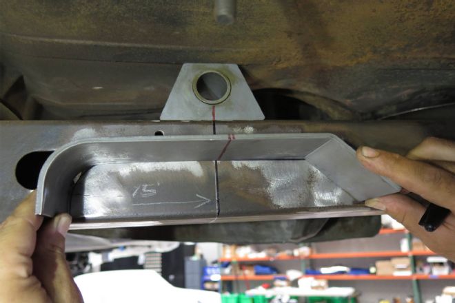
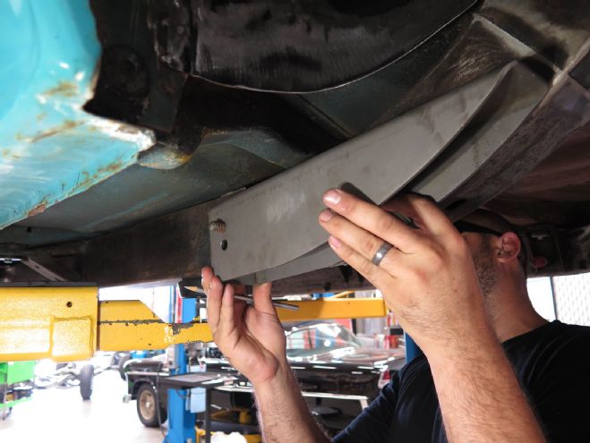 Mocking up the location of the front spring pocket mount. The bolt hole in the pocket must be centered in the frame access hole.
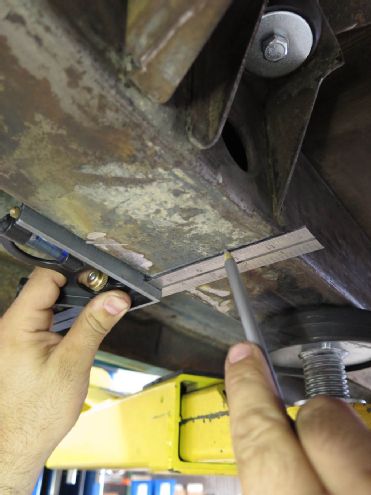 Once its location was determined, the position of the forward edge of the spring pocket was marked on the bottom face of the frame.
 A pattern was made of the pocket mount, which was then transferred onto the underside of the chassis rail.
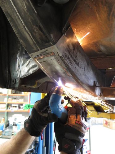 The corresponding section of the frame was then removed. This can be done with a cut-off wheel in a grinder, or, as we did, using a Miller 375 Xtreme plasma cutter.
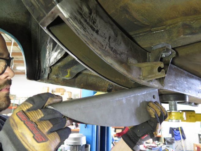
 The frame section was then removed.
The hole will likely need to be trimmed to ensure the spring pocket is a snug fit.
The frame section was then removed.
The hole will likely need to be trimmed to ensure the spring pocket is a snug fit.
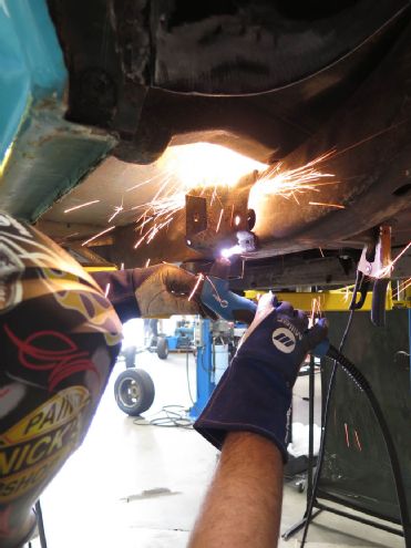
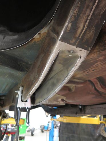 Once happy with the fit, the pocket was tacked in place using a Millermatic 190 MIG welder.
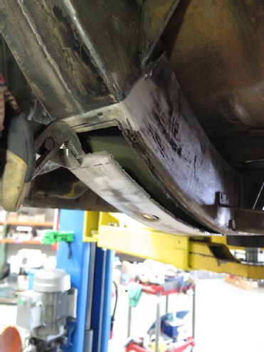
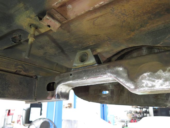
 The new rear spring notch is located next, centered off the new upper shackle mount, which in turn is located 15 inches forward of the outside rear edge of the framerail.
 The notch was first tacked in place—note the clamp used to align the sides of the chassis rails as they spread slightly when the section was removed.
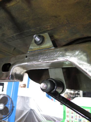
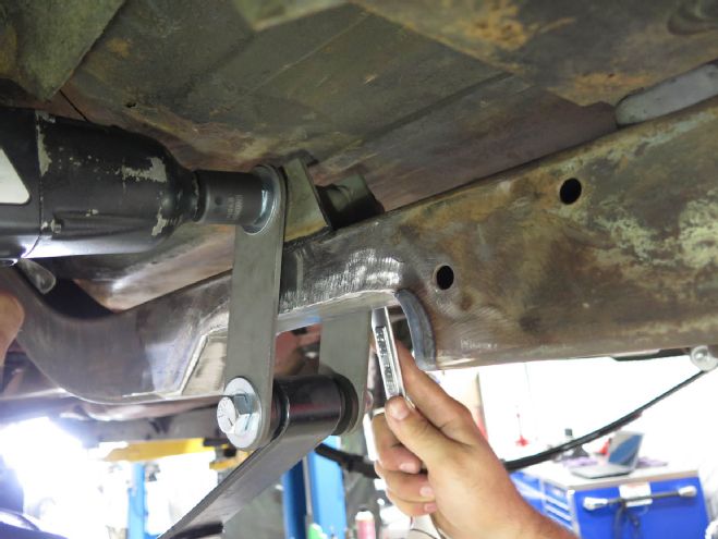
 The notch plates and spring shackle mounts were then fully welded.
The new dropped leaf springs were installed on new shackles, first at the rear …
The notch plates and spring shackle mounts were then fully welded.
The new dropped leaf springs were installed on new shackles, first at the rear …
 … then in the front pockets. There’s no shackle here.
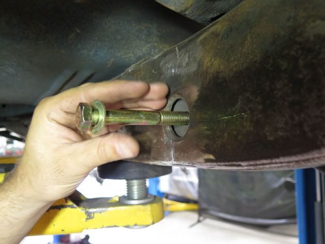 The front spring bolt locates through the access hole in the chassis rail.
 With front and rear mounting bolts in place, all were tightened.
 The CPP/Currie Crate 9-inch rearend was installed next, using CPP’s tie plates (shock mount plate with welded stud).
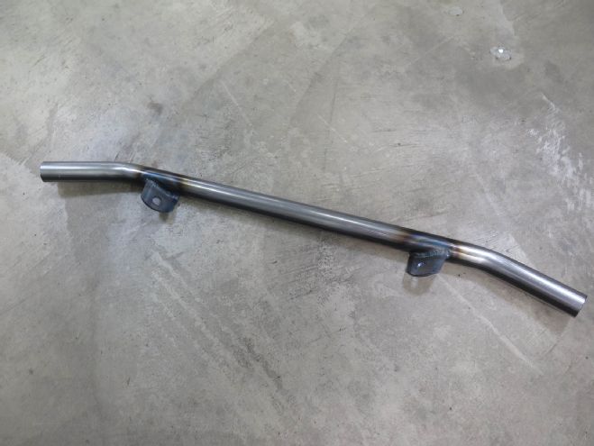 This project used CPP’s weld-in rear shock crossmember, though a bolt-in Rear End Conversion Kit is also available.
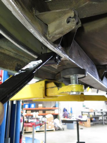
 The crossmember and adjustable aluminum shocks were mocked in place …
 … and marked for cutting to length.
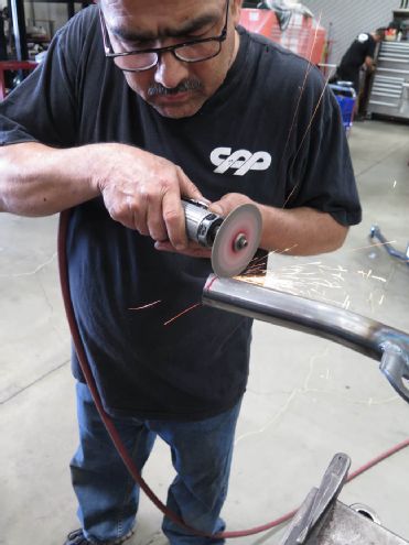 The crossemember was angle-trimmed for a precise fit.
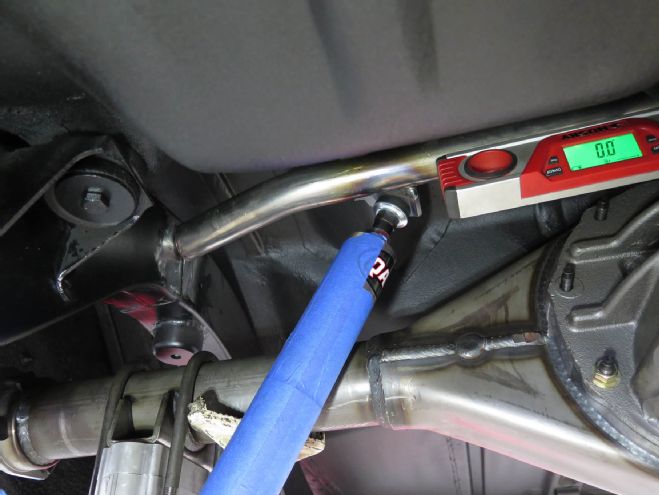
Located perpendicular to chassis and perfectly horizontal in relation to the chassis, the crossemember is ready to be welded. Note the rearend is as high as it can go (bumpstops will actually stop it going this high) to ensure the shocks don’t bottom out before the suspension reaches full compression.
The crossemember was angle-trimmed for a precise fit.
Located perpendicular to chassis and perfectly horizontal in relation to the chassis, the crossemember is ready to be welded. Note the rearend is as high as it can go (bumpstops will actually stop it going this high) to ensure the shocks don’t bottom out before the suspension reaches full compression.
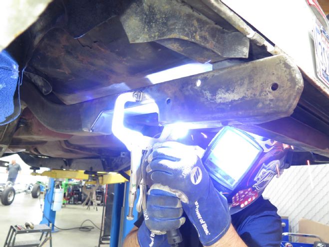
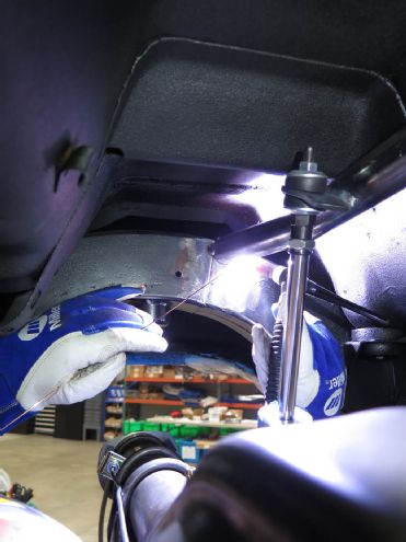 Once happy with the location and fit, the crossemember was TIG-welded in place.
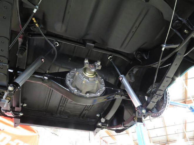
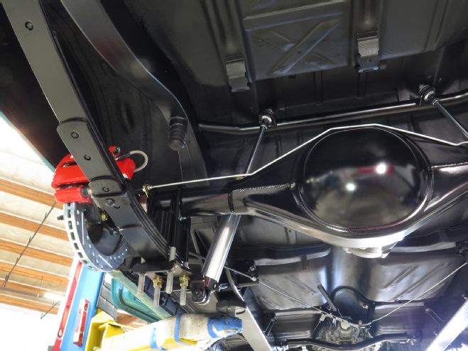
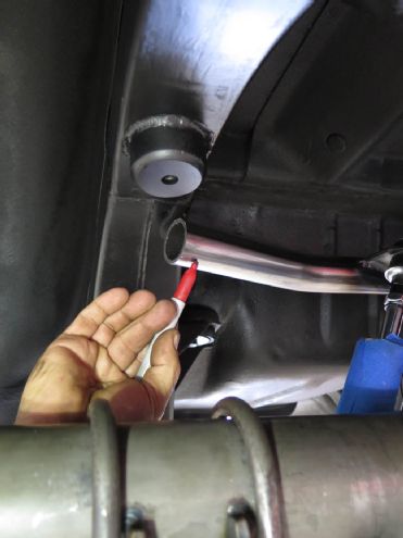
Once everything was removed, painted, powdercoated, and re-installed with new brake lines, the installation looked like this. Note the bumpstops above the rearend, as mentioned above.
Once happy with the location and fit, the crossemember was TIG-welded in place.
Once everything was removed, painted, powdercoated, and re-installed with new brake lines, the installation looked like this. Note the bumpstops above the rearend, as mentioned above.
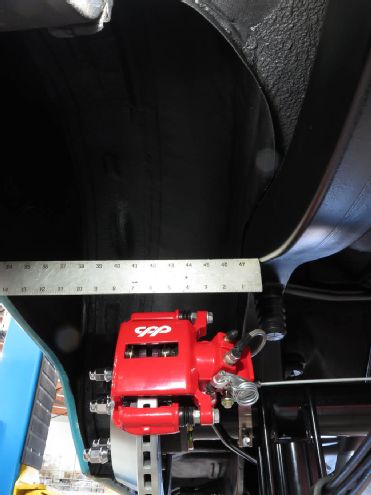 From outer framerail to inner rear quarter-panel, the space available has increased by 2-5/8 inches per side (up to 15 inches total width), allowing the use of wheels in excess of 10 inches wide. The 1955 will run 20x11s, with room to spare with the addition of the mini wheel tubs also fitted.