Making brake lines is one of those tasks I always dread. I don't do it often enough to be very good at it, I don't have the right tools, and it never comes out nearly as nice as I expect it to. With all the work that's going into my C10, however, I'm bound and determined to change that with this build. Ever one for a good challenge, I decided to make this my "cause celebre" with which I would attack at all angles until I figured out just what it took to make the ultimate brake line. It turned out it was pretty simple really; just a manner of proper technique and a few handy tools.
As usual, I was doing something wrong and that no doubt contributed to my past frustration and lack of confidence when it came to flarin' and bendin' lines. Putting my Cro-Magnon reflex aside, I decided to follow Inline Tube's instructions when it came to cutting and prepping brake tubing. Turns out, using a standard tubing cutter (like what you'd use to cut copper plumbing lines in your house) isn't the way to do it. Now you tell me?!
As it happens, most tubing cutters are rather dull and when they're used to cut brake lines, particularly stainless steel, they work harden the end. This results in a flare that splits due to the metal's lack of malleability. Instead, Inline Tube recommends using a cutoff wheel on a die grinder to slice the tubing down. Then, after careful deburring and chamfering, the tubing can be easily flared to either the traditional 45-degree double flare or the more contemporary 37-degree AN flare.
Those perfect bends, however, are a different story, but one that's not lost using the same approach. The key is having the right tools on hand. It turned out that Inline Tube had hooked us up in the CCT Tech Center in the past and all I had to do was look around and the keys to building the best brake lines possible were within reach. Their Small Radius Bender coupled with their Tri Bender Tool is all a guy needs short of a tape measure and a marking pen to knock out brake lines that follow every curved nuance in a truck's chassis.
Last month, I finished up with a pair of Wilwood master cylinders on the firewall of my C10. This month, we'll plumb them up to their respective outputs and hopefully shine a light on the best methods to making custom brake lines.
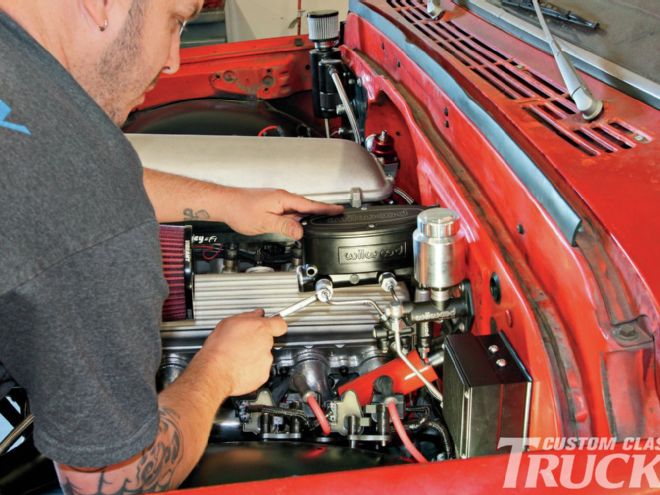
 1. Here’s where we left off last month after the pedals were installed.
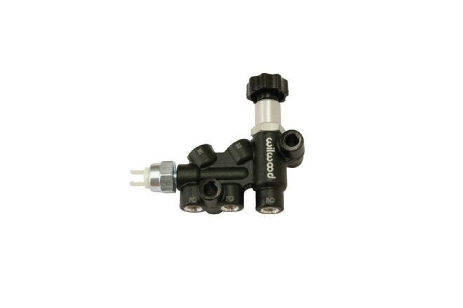 2. We’ll begin by mounting the adjustable proportioning valve and use the prefabbed brake lines to mate it to the master cylinder.
 3. We’ll begin by mounting the adjustable proportioning valve and use the prefabbed brake lines to mate it to the master cylinder.
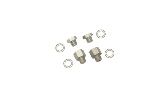 4. Wilwood’s master cylinder features dual outlets and comes complete with plugs and adapters, saving a trip to the auto parts store.
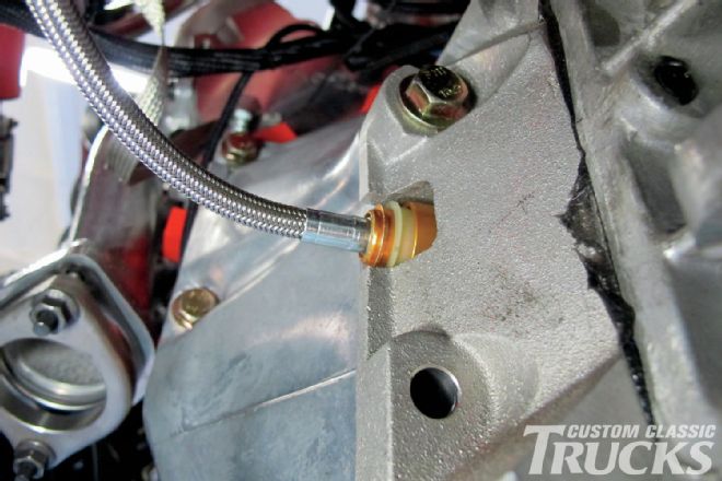
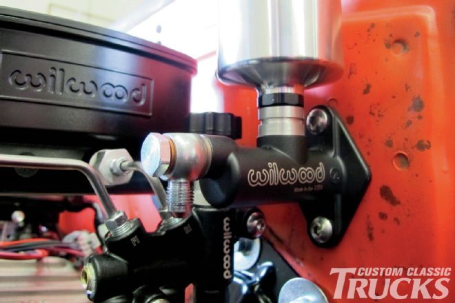 5. Our Wilwood clutch master cylinder features a 1⁄8-27 NPT outlet, which allows us to use a banjo bolt and -3AN fitting to run the hardline straight down the firewall.
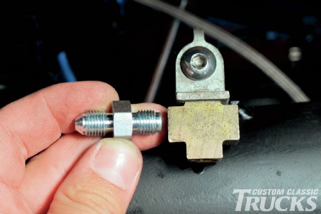
 6. To mate a hardline to a male AN fitting, it’s necessary to make a 37-degree single flare on the line in conjunction with a nut and sleeve of the corresponding size.
 7. To mate a hardline to a male AN fitting, it’s necessary to make a 37-degree single flare on the line in conjunction with a nut and sleeve of the corresponding size.
8. Notice how the sleeve has the same 37-degree flare machined into the top? This is what compresses the flare in the line against the fitting to create a seal. It also supports the tubing, since the single flare requires extra support when compared to a standard brake inverted flare.
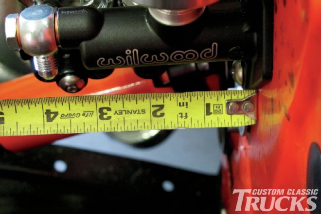
9. With the first end of our clutch hydraulic line finished, it’s time to start bending the OEM steel ¼-inch tubing to shape. The first bend is going to send the line toward the firewall. A quick measurement is taken between the fitting and the firewall…
7. To mate a hardline to a male AN fitting, it’s necessary to make a 37-degree single flare on the line in conjunction with a nut and sleeve of the corresponding size.
8. Notice how the sleeve has the same 37-degree flare machined into the top? This is what compresses the flare in the line against the fitting to create a seal. It also supports the tubing, since the single flare requires extra support when compared to a standard brake inverted flare.
9. With the first end of our clutch hydraulic line finished, it’s time to start bending the OEM steel ¼-inch tubing to shape. The first bend is going to send the line toward the firewall. A quick measurement is taken between the fitting and the firewall…
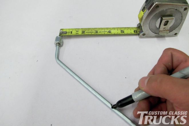 10. …before it’s used to then mark the line. Note that a 45-degree bend has already been made just below the AN fitting; the location of this bend is not critical, but the distance between the fitting and the firewall is.
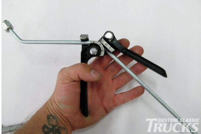 11. Next, using the line as my starting point, I created another 45-degree bend in the line to bring it back parallel with the section exiting the master cylinder. Note the corresponding lines on the bender, telling me that I’ve reached 45-degrees.
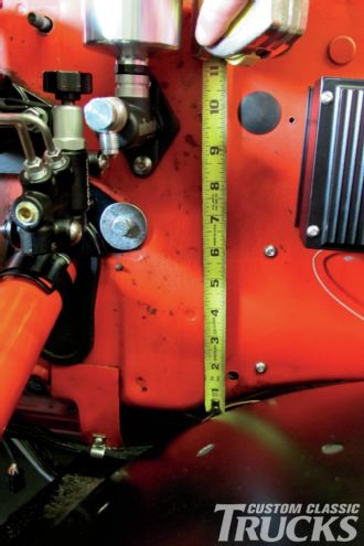 12. Another measurement is taken, this time from the bottom of the outlet fitting to the bottom of the firewall.
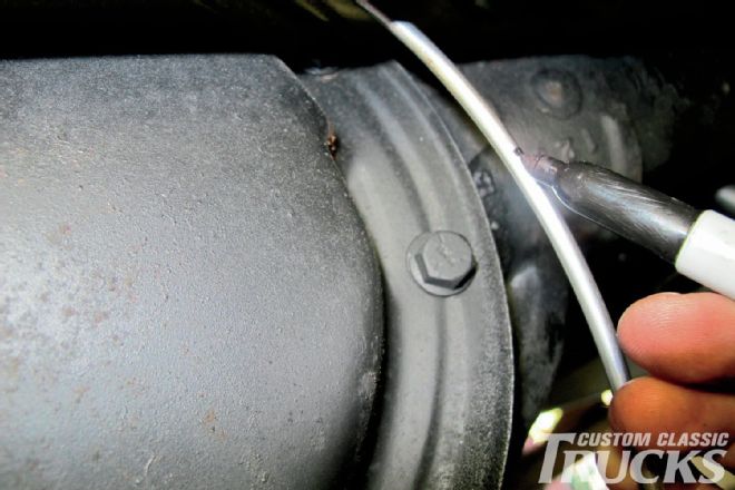
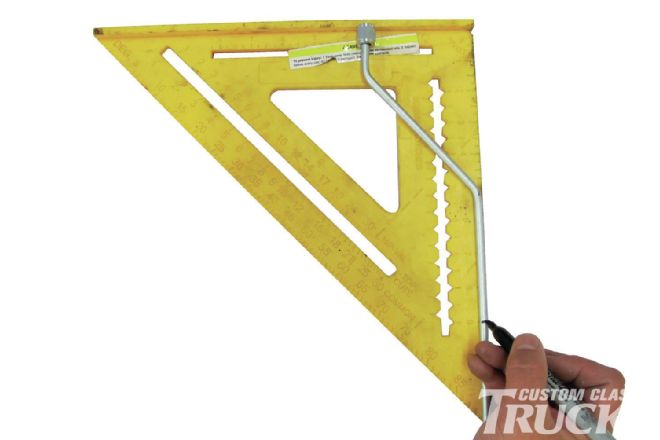 13. A speed square is an easy way to mark distances on curved lines, such as this one. Simply place the fitting flush at the top and mark the distance where the next bend needs to be made.
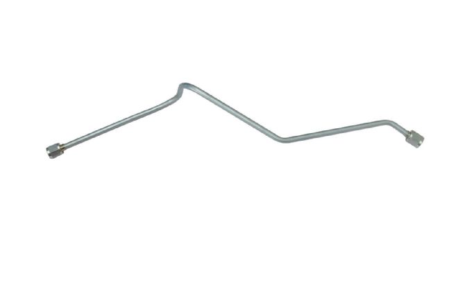 14. The last two bends are a bit tricky as it requires a 90-degree bend perpendicular to the last two bends followed by another 90-degree bend nearly parallel with the first. This is where I usually screw up, but this time I got lucky! Another 37-degree flare, nut, and tube finish off the hardline.
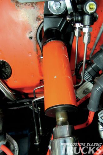
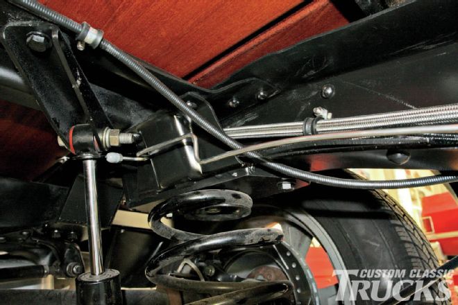
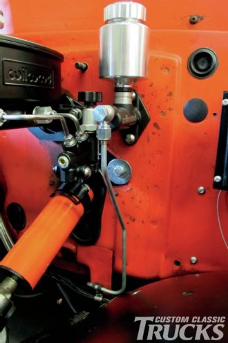 15. Here’s what the line looks like installed on the clutch master cylinder. A rubber clamp helps support the line as AN flares aren’t known for their strength when it comes to vibration and stress.
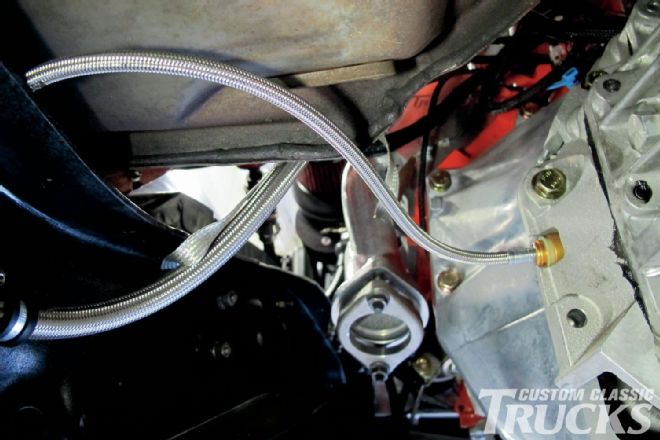
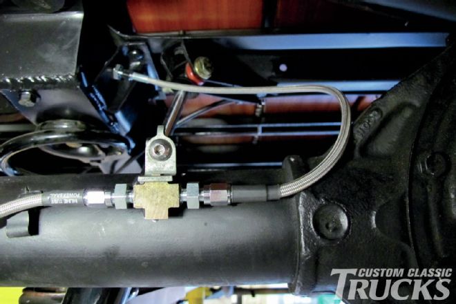
 16. Down under the cab, another rubber clamp isolates the line at the AN union that mates the hardline to the braided stainless hose.
 17. From there, the -4AN hose attaches to the hydraulic throwout bearing via a quick-disconnect, completing our clutch’s hydraulic system.
 18. From there, the -4AN hose attaches to the hydraulic throwout bearing via a quick-disconnect, completing our clutch’s hydraulic system.
 19. With the clutch line complete, it’s time to start on the brake lines.
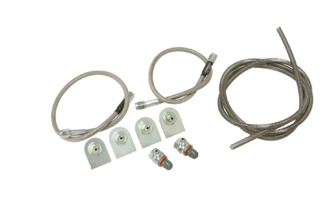 20. For this, we’re going to be using Inline Tube’s stainless steel brake line set. The kit comes with everything needed to plumb a standard brake job, including stainless braided hose, spring wrap, brake line tabs, through-frame fittings, banjo bolts, and a myriad of fittings. Not pictured is the 3⁄16-inch stainless steel line we’ll be using that Inline Tube sells in 6-foot lengths (30 feet is standard in their kit).
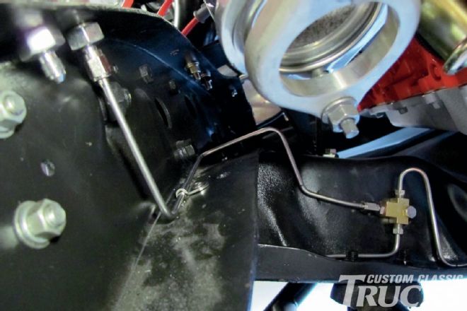
 21. When it comes to building the brake lines of any vehicle, there really isn’t a rule regarding where to start. Since it’s not something I do very often, I like to start with a small section underneath the truck before tackling the harder sections, like up the firewall to the master cylinder, where your handiwork (or lack thereof!) is visible. I decided to use the T fitting I installed on the front crossmember as my jumping-off point.
 22. Next, I sorted out the brake hoses at both front calipers. Inline Tube provided a pair of their Power Braid stainless steel braided hose, which eliminates that spongy feel rubber hoses can suffer from and offers the safety that only braided stainless steel hose can. At the caliper end, a banjo fitting mates directly to the -3AN braided hose, while on the opposite end, a threaded adapter fitting is used to secure the end of the hose directly to the tab on the frame instead of using the old-style C-clip.
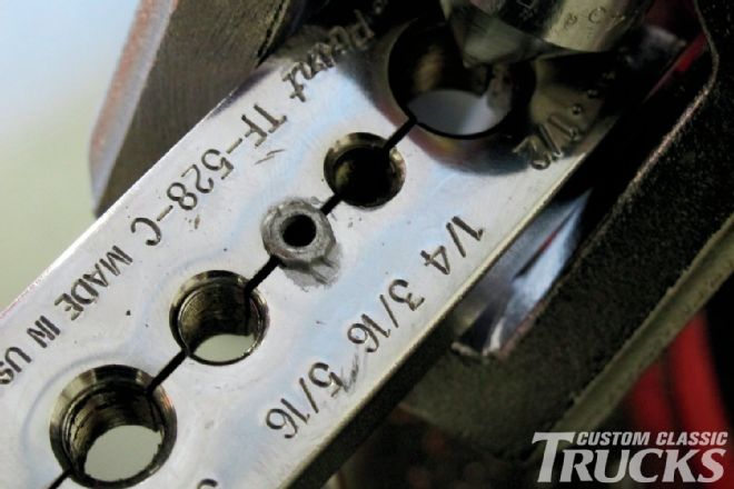
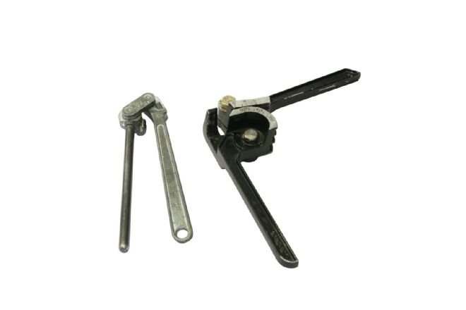 23. When it comes to bending brake lines, especially stainless steel, a couple good tubing benders are a must and Inline Tube has you covered. I really like their Small Radius Bender (left), which will bend 3⁄16-inch tubing in a 11⁄8-inch diameter circle. Their Tri Bender Tool is a good all-around bender for 3⁄16-, ¼-, 5⁄16-, and 3⁄8-inch tubing.
24. I used the Small Radius Bender almost exclusively when it came time to bending the tight radii bends, including where the front brake lines met the hose.
23. When it comes to bending brake lines, especially stainless steel, a couple good tubing benders are a must and Inline Tube has you covered. I really like their Small Radius Bender (left), which will bend 3⁄16-inch tubing in a 11⁄8-inch diameter circle. Their Tri Bender Tool is a good all-around bender for 3⁄16-, ¼-, 5⁄16-, and 3⁄8-inch tubing.
24. I used the Small Radius Bender almost exclusively when it came time to bending the tight radii bends, including where the front brake lines met the hose.
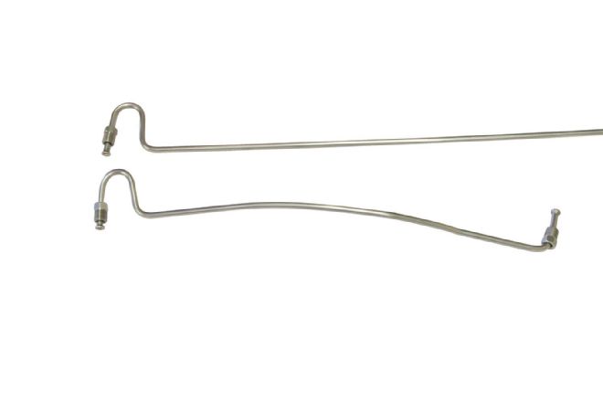 25. I made the driver side hardline first, then mimicked the shape for the passenger’s side. Note the tight radius on the hose end of the line.
 26. Some bends are not possible to make with a tool and require more archaic methods. Here, I gently persuade the line to follow the curvature of the crossmember.
 27. A section of TIG welding rod works great for creating a template before bending a tricky section, such as where the passenger’s side hardline meets the T. Note that I rotated the T 90-degrees counterclockwise so that the inlet can sit protected behind the crossmember like the left- and right-side hardlines.
 28. Using the welding rod template and Small Radius Bender, I was able to bend a nice, tight radius in my line to match the one on the opposite end.
 29. Using the welding rod template and Small Radius Bender, I was able to bend a nice, tight radius in my line to match the one on the opposite end.
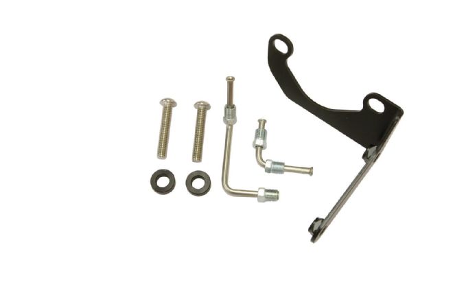
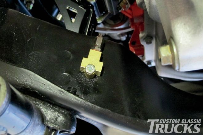
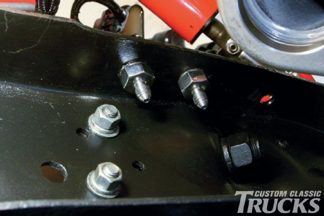 30. Instead of trying to route the front and rear brake lines around the framerail, I decided that a pair of Thru-Frame Fittings installed on the top of the framerail would be a cleaner alternative.
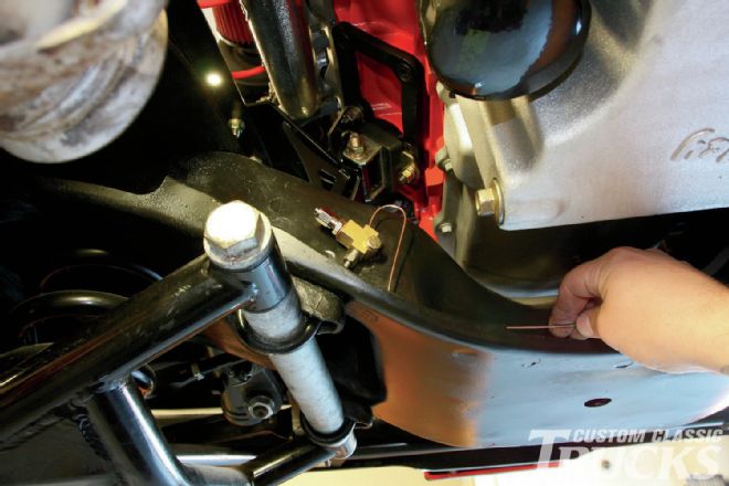
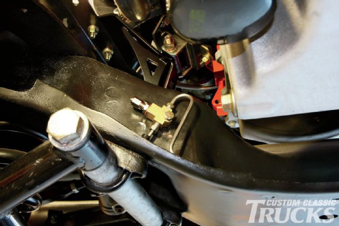
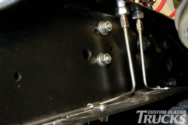
 31. Here’s the front brake line inlet from the Thru-Frame Fitting to the T. Note the marks on the bends that I used to get the dimensions correct. This line also features AN fittings as opposed to the left- and right-side lines, which use traditional inverted flare fittings. This is a simple byproduct of the type of fittings used and what we had on hand.
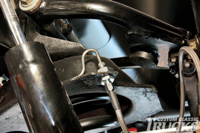
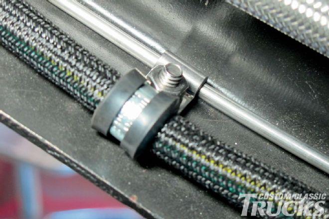
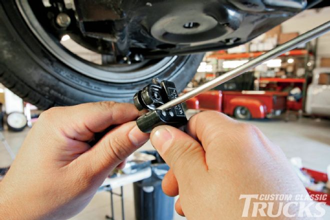
 32. Since a 37-degree AN flare is not as strong as an inverted flare, a stainless line clamp was used to secure the line directly to the bottom of the framerail.
 33. With the front brake lines sorted, it’s time to do the same for the rear. Since we’re running disc brakes at all four corners, it’s possible to use 3⁄16-inch brake line throughout. The first bend is measured, marked, and made, before the line is secured near the connection with another stainless line clamp.
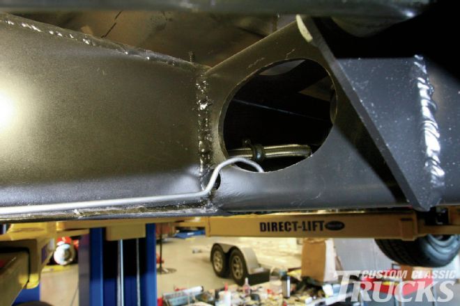 34. While the tubing bender was irreplaceable once again, it was also necessary to make a few improvisational bends when it came to routing the rear brake line along the bottom of the framerail. Here, the line is bent over the rear crossmember and checked for fitment outside of the boxing plate before it’s slid inside the confines of the framerail.
 35. Savvy readers might notice that I opted to run the rear brake line down the driver side framerail, instead of across the front crossmember and down the passenger side. There’s no reason it can’t be done differently than the factory.
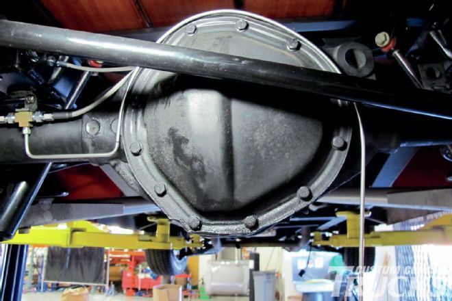
 36. Another Thru-Frame Fitting was mounted in a stock hole on the chassis, allowing the stainless hardline to mate with the braided line that will connect to the rearend.
 37. More stainless clamps secured the rear line, using the same hardware as the clamps securing the rear lighting harness.
 38. I welded a tab onto the rearend before mounting another T fitting. This one will also receives AN fittings.
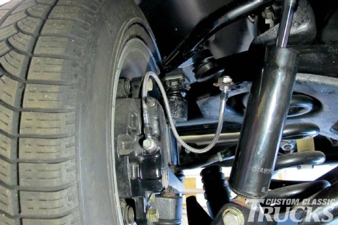
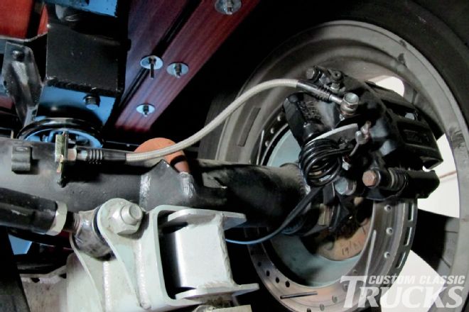
 39. A Power Braid hose connects the left rear caliper to the T on the rearend, held in place with another line clamp that was mounted to the trailing arm bracket to prevent the hose from contacting the framerail during suspension compression.
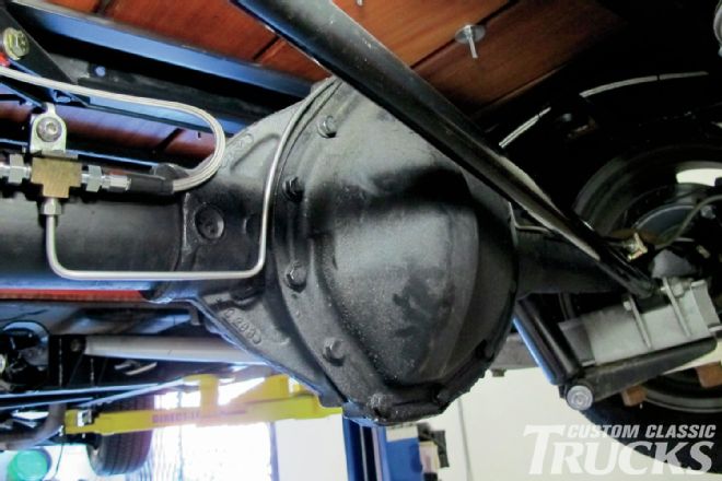
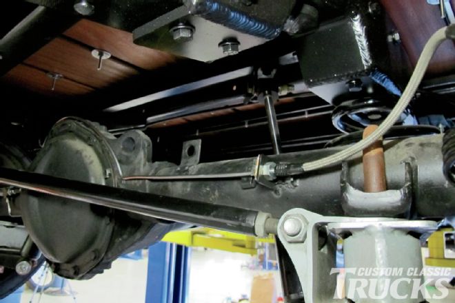
 40. Another Power Braid hose mates the rear brake line to the T on the rearend. Notice I mounted the T so that the line attaches horizontally in order to prevent it from contacting the bed floor during suspension travel.
 41. Over on the passenger side of the rearend, the preexisting stainless braided hose that came with the disc brake kit will be used, attached to a tab welded to the rearend housing. The hose will attach to a hard line, due to its distance from the T.
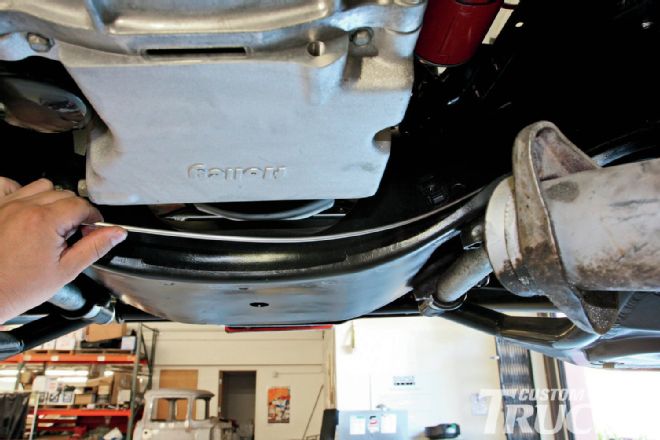
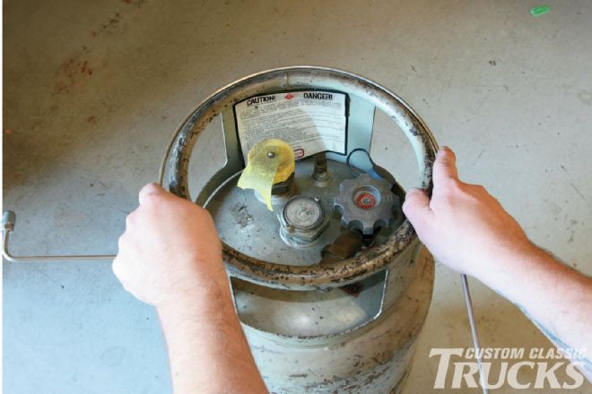 42. First, the distance from the T to the center section is measured and a tight 90-degree bend is made. Then, a suitable stand-in for the center section, in this case a propane tank for a forklift, is used to get the rough shape.
43. Next, the bend is checked against the rearend, not too bad!
42. First, the distance from the T to the center section is measured and a tight 90-degree bend is made. Then, a suitable stand-in for the center section, in this case a propane tank for a forklift, is used to get the rough shape.
43. Next, the bend is checked against the rearend, not too bad!
 44. One more bend is necessary in order to get the line over to the right side hose, so after a quick mark…
 45. …another tight 90-degree bend is made and the line is complete.
46. …another tight 90-degree bend is made and the line is complete.
47. The two lines I was most worried about turned out to be the easiest, in part I think because I saved them for last. Having spent two days bending lines didn’t hurt! I made a template using welding rod, bent one line up, and once happy with it made the other to match. A bit of trimming was necessary as the front line was slightly closer to the master cylinder due to the curvature of the frame, but once in place, I had two perfectly symmetrical lines.
45. …another tight 90-degree bend is made and the line is complete.
46. …another tight 90-degree bend is made and the line is complete.
47. The two lines I was most worried about turned out to be the easiest, in part I think because I saved them for last. Having spent two days bending lines didn’t hurt! I made a template using welding rod, bent one line up, and once happy with it made the other to match. A bit of trimming was necessary as the front line was slightly closer to the master cylinder due to the curvature of the frame, but once in place, I had two perfectly symmetrical lines.
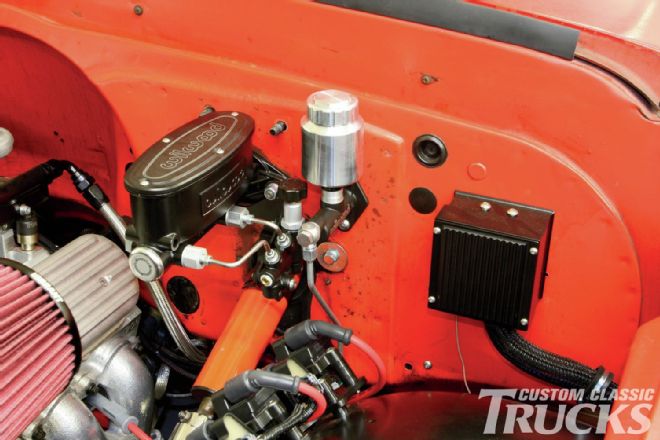
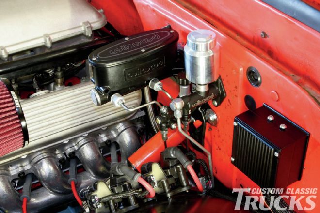 48. The finished brake lines combined with the new Wilwood master cylinders look the business when compared to the old setup and better match the performance and aesthetic of the rest of the truck.
Flawless Flares
Making flawless flares is easy if you have the right tools. Here's how we made all our flares on the C10.
 1. In the past, I’ve always used a tubing cutter when it came to cutting brake lines. Don’t do that! As it turns out, the cutter can actually harden the end causing flaring to be very difficult. The first few times I made flares in stainless steel, I used a tubing cutter and the flares split, every time.
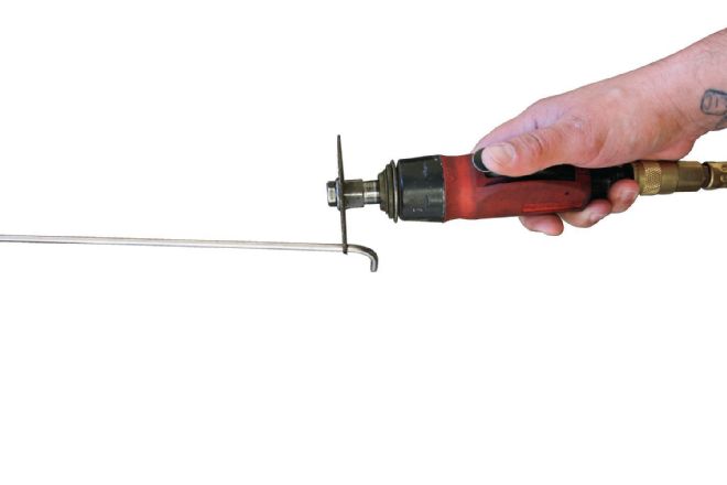 2. Instead, use a metal fiber cutoff wheel.
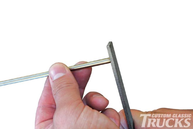 3. Then use a file to deburr and chamfer the outside edge.
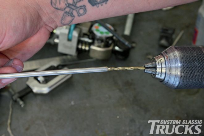 4. A drill bit that corresponds with the ID of the tubing works good to deburr the inside edge.
AN Flares
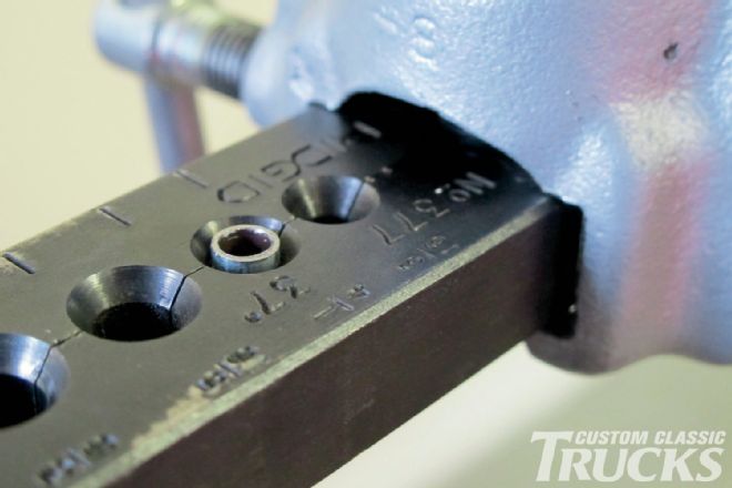
 5. Making AN flares is fairly simple as it only involves making a single 37-degree flare, but even these can suffer if the aforementioned prep isn’t followed. First, the tube is inserted in the tool (in our case, a Ridgid item available locally) flush with the top of the die. A dab of antiseize will make the next step even easier.
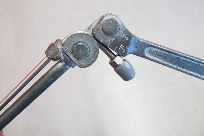
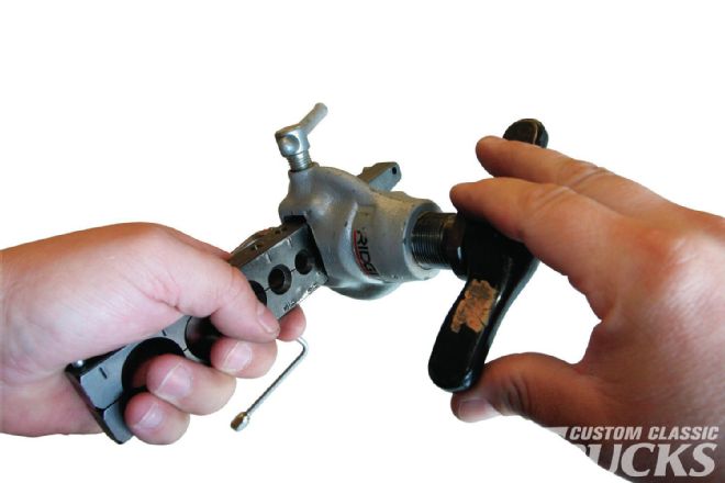 6. Then the handle is tightened onto the die, locking the tubing in place. The male form is then drawn down onto the tube and die, forming the flare.
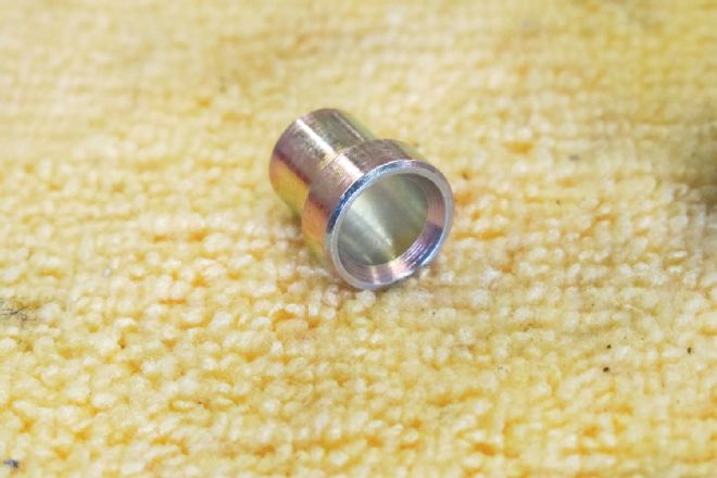
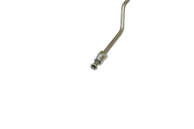
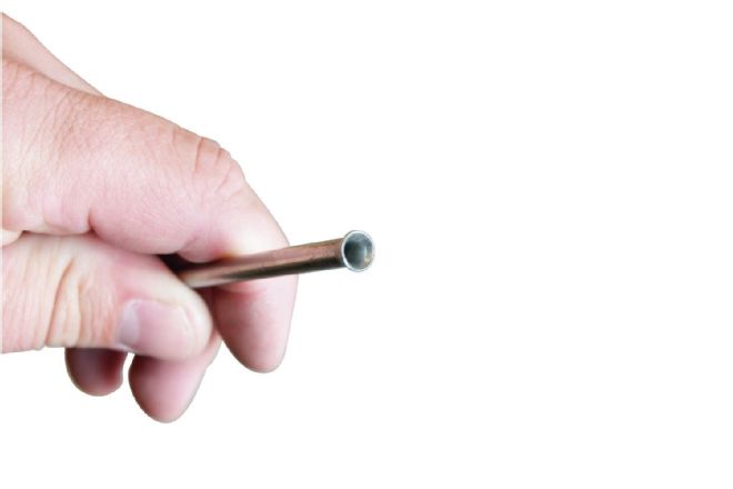 7. Here’s a perfect 37-degree AN flare.
45-degree Double Flares
Making 45-degree double or inverted brake flares is slightly more complicated, especially when using stainless steel. I've found that careful preparation, a little antiseize, and resisting the temptation to torque down hard on the flaring tool yields consistent flares every time. We have two tools in the tech center and both do the job well, but the Eastwood tool is by far faster and simpler. The one drawback it has is that when a flare needs to be made near a bend, due to the way it captures the tube, it either needs to be made before the bend is made, or the traditional tool needs to be used. I learned this by mistake!
 8. Don’t forget to install the nut and sleeve before you make the flare!
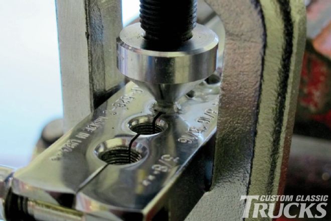
 9. Using a traditional 45-degree double flaring tool available from any auto parts house, the first step is to insert the tubing flush with the top of the holder and place the die over the tube. Then, the die is forced over the tube, effectively forming the first flare of the double flare.
 10. It looks distorted, but this is what the first half of a double flare looks like. That’s antiseize on the tubing, which helps the flare form smoothly, cutting down on the likelihood of cracking.
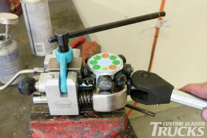
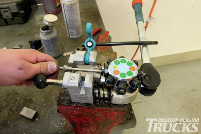 12. Making 45-degree double flares has never been easier than with Eastwood’s Professional Brake Tubing Flaring Tool. It’s literally as easy as 1-2-3. First, the brake tubing is prepped using the same method mentioned earlier. Then, it’s inserted between the corresponding die set to hold it in place.
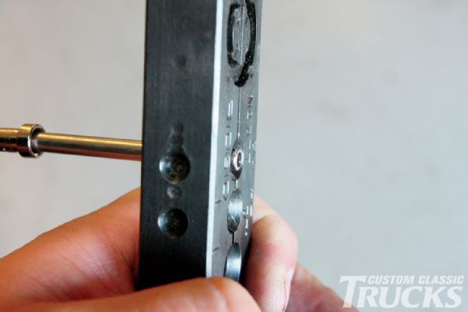
 13. The Eastwood tool has a rotating turret that labels the operations step-by-step. The first operation is to check the amount of “stickout” of the tubing before the T handle is clamped securely against the die set.
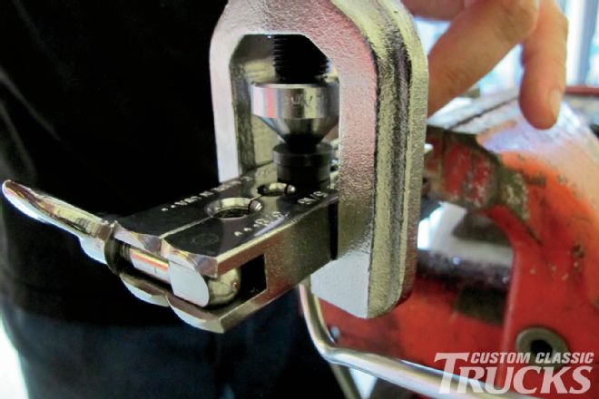
11. Next, the die is set aside and the second half of the flare, the inverted portion is made by drawing the mandrel down onto the tube.
13. The Eastwood tool has a rotating turret that labels the operations step-by-step. The first operation is to check the amount of “stickout” of the tubing before the T handle is clamped securely against the die set.
11. Next, the die is set aside and the second half of the flare, the inverted portion is made by drawing the mandrel down onto the tube.
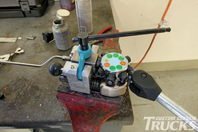
 14. Next, the first flare is created using the die marked “OP 1.” A bit of antiseize never hurts!
 15. Next, the first flare is created using the die marked “OP 1.” A bit of antiseize never hurts!
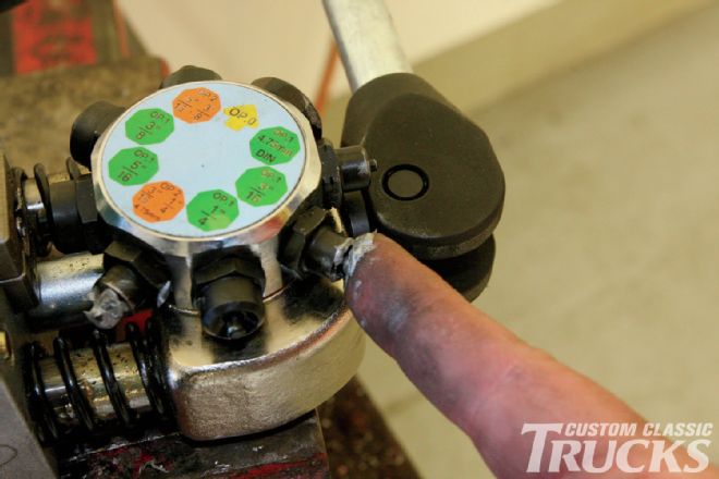
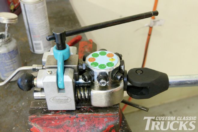 16. Then, the handle is released, the turret turned to the corresponding die marked “OP 2,” and the handle is again compressed to finalize the second flaring operation, thereby creating the inverted flare.
The "Eastwood" Way
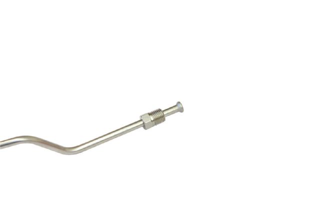
 17. And there you have it! Perfect double flares every time, even on stainless tubing.
 18. And there you have it! Perfect double flares every time, even on stainless tubing.