With the exception of when appearance is an issue—using a steering box on a traditional rod, for example—the use of a steering box or rack-and-pinion is down to personal choice when there's an option of using either. And when it comes to Tri-Five Chevys, there's definitely a choice. More than one manufacturer offers new steering boxes for these cars, and in fact that is what was removed to fit the Unisteer rack-and-pinion, as the owner of this blown big-block–equipped 1955 wanted the responsiveness and just over two-and-a-half turns lock-to-lock that the rack-and-pinion offers.
Installing the kit is actually very simple, a bolt-in deal. What takes the time is hooking the rack-and-pinion to the steering column, and removing the original steering assembly. This car had no original steering column or steering box to disassemble. On a stocker the inner column shaft is part of the steering box, and is removed from the car as a single unit. As mentioned, this particular car already had an aftermarket steering box installed, making removal simpler.
Unisteer offers its Tri-Five rack-and-pinion kit in either manual or power options, and in black or chrome. All are designed to fit a Tri-Five with a small-block Chevy engine, though an LT1-specific kit is also offered. All will fit cars equipped with dropped spindles. The installation we're following at Jimenez Bros. Customs (JBC) is on a big-block–equipped 1955. The main difference is routing the steering shafts, as the physical size of the big-block and its headers makes things awkward. The actual rack-and-pinion kit fit with no clearance issues.
Unisteer actually offers a shorty header, made by Sanderson, to complement its kits, as well as a Tri-Five steering shaft kit, comprising two universal joints and one intermediate shaft. Also available is a bushing to convert stock, non-shift steering columns for use with the rack-and-pinion kit. JBC fabricated a steering system using two intermediate shafts and a support bearing in order to clear the big-block's headers. Another option, as an aftermarket steering column with a 1-inch DD hollow shaft was used, would have been to insert a length of 3/4-inch DD shaft into the column shaft, and pin or bolt it in place. This would have eliminated the support bearing. With the weight of a blown big-block and manual steering, however, the option JBC chose is stronger and safer.
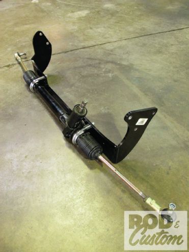
 1. Here’s the Unisteer Tri-Five kit, comprising the modified Saginaw rack-and-pinion, outer tie-rod ends, mounting bracket and hardware, and new steering arms. It uses a 16mm DD input, its 5 inches of travel providing 2.65 turns lock-to-lock.
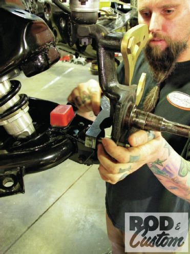
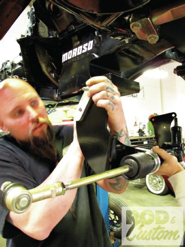
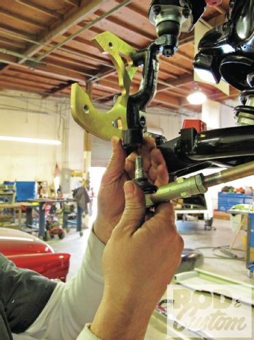
 2. The first order of business was to remove the existing steering box, held in place by three bolts through the chassis rail. A puller is required to remove the pitman arm.
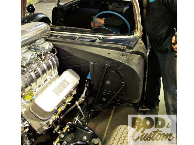
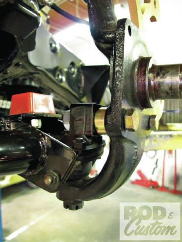
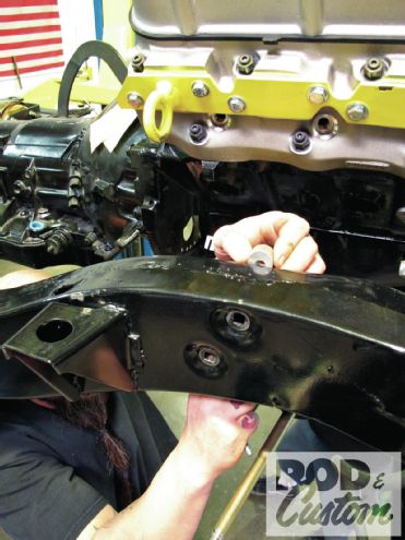
 3. Note the oil pan on the big-block was fabricated to clear the centerlink of the original steering. While the Unisteer kit is designed for Tri-Fives with small-blocks, it will fit most applications that have enough clearance for the original centerlink.
 4. The outer tie rods were removed from the steering arms, which in turn were removed from the spindles. Once the idler arm was removed from the passenger side of the chassis, the old steering assembly was removed.
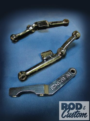 5. Here are the stock steering arms (top) compared to one of the Unisteer versions.
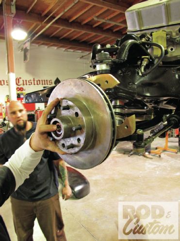
 6. The rotor, caliper, and hub were removed for ease of installation, and the new steering arms installed.
 7. Note the spacer is used between the steering arm and spindle.
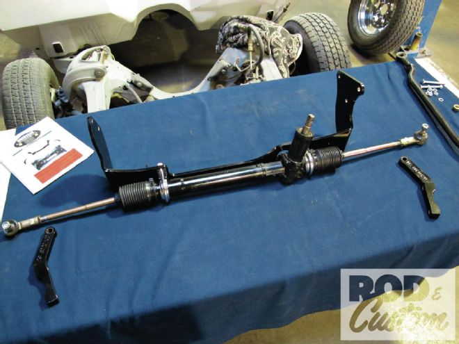
 8. The new rack-and-pinion and mounting bracket ready for installation.
 9. Owing to manufacturing variables over 50 years ago, not all chassis have the same dimensions. Jimenez Bros. Customs machined these spacers to fit between the Unisteer bracket and the chassis ’rails, though by all means not all Tri-Fives require them.
 10. This is the passenger side where the bracket bolts through the original idler arm mounting holes.
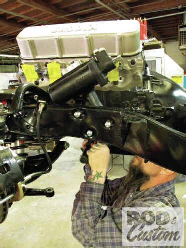
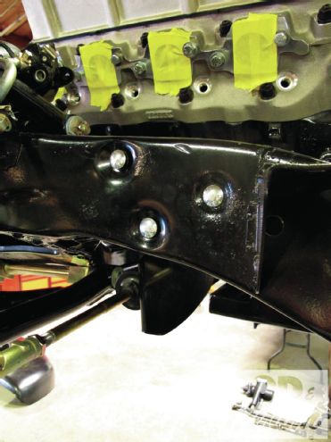 11. The three steering box holes are used to mount the bracket on the driver side.
12. The three steering box holes are used to mount the bracket on the driver side.
11. The three steering box holes are used to mount the bracket on the driver side.
12. The three steering box holes are used to mount the bracket on the driver side.
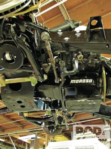
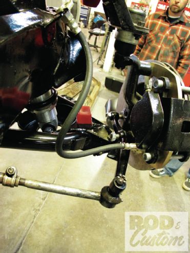
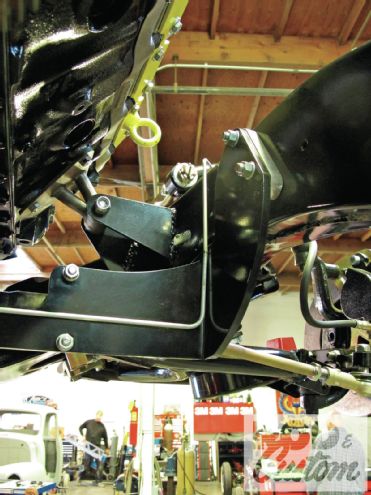
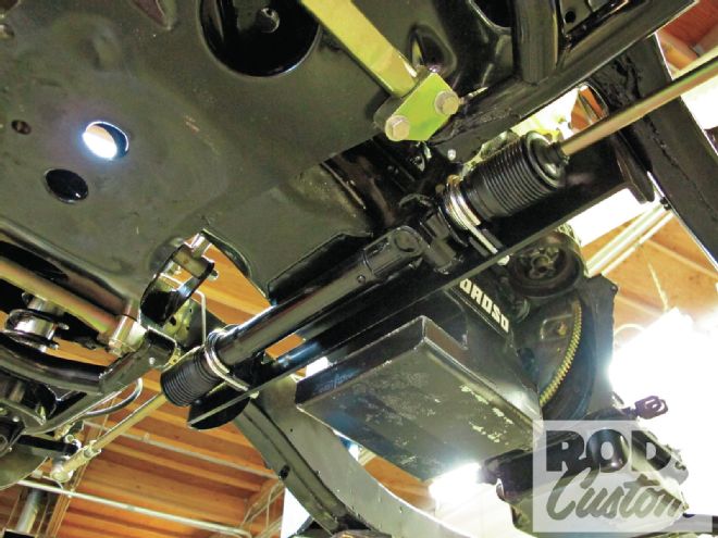 13. Viewed from below, you can clearly see how the rack-and-pinion fits where the old centerlink was. Note also how the inner pivots of the tie rods (inside the rubber boots) on the narrowed rack align with the lower control arm pivots, virtually eliminating bumpsteer.
 14. With the steering rack centered (turn the input shaft fully one way, then fully the other, then halfway back) and the tie-rod ends threaded onto the tie rods an equal amount, they were installed on the spindles.
 15. The rotors and calipers were re-installed next.
 16. The finished assembly, although the tie-rod ends aren’t tightened fully and may need adjusting during the alignment stage.
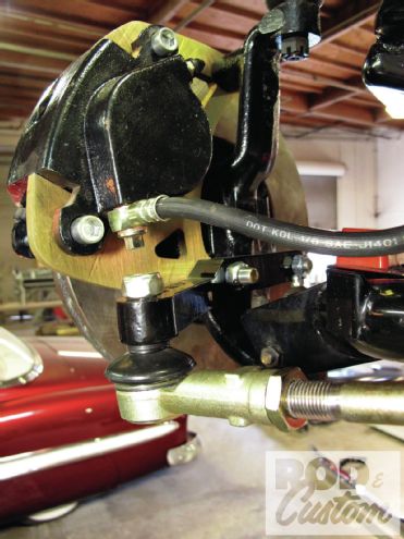
 17. Here’s the passenger side, looking forward, complete with new brake line.
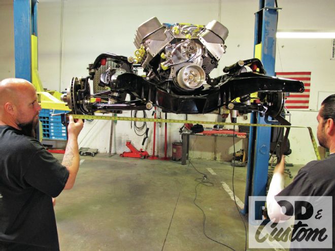 18. The car will get aligned once completed, but the guys at JBC got it close by clamping a straightedge to each rotor, then measuring the distance between them, both fore and aft of the spindles, and adjusting the tie-rod ends to provide slight toe-in.
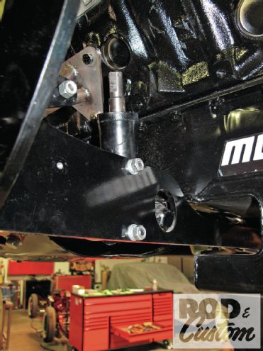 19. The DD input shaft on the rack-and-pinion is vertical on this installation.
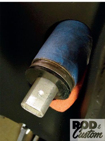
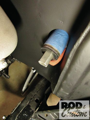 20. An aftermarket steering column of unknown parentage was used. It uses a DD shaft. You can make out where the set screw was tightened once the universal joint (U/J) was installed. The shaft is correctly installed when its end is flush with the bottom of the hole in the U/J. Any farther in and the shaft will cause the U/J to bind.
 21. The shaft is then drilled to leave an indent, so that the set screw (which should always be installed using thread locker) prevents the U/J from slipping off the shaft.
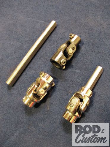 22. The components required to maneuver from the bottom of the steering column to the rack-and-pinion: two short lengths of DD stainless shaft, two DD-to-DD U/Js, and one DD reducer U/J to fit the inner steering column DD shaft.
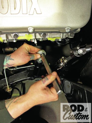
 23. The reducer DD U/J and the first section of DD shaft were installed.
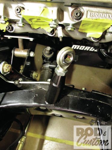 24. Though we’re not showing them here, the headers were installed prior to plotting the route the steering shaft and U/Js would take. This route necessitated the use of a Heim joint to support the second sections of shaft.
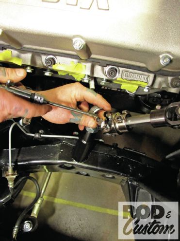
 25. The second section of stainless shaft was passed through the Heim joint prior to hooking it up to the U/Js.
 26. JBC opted to drill the DD shaft then tap it for extra set screw security.
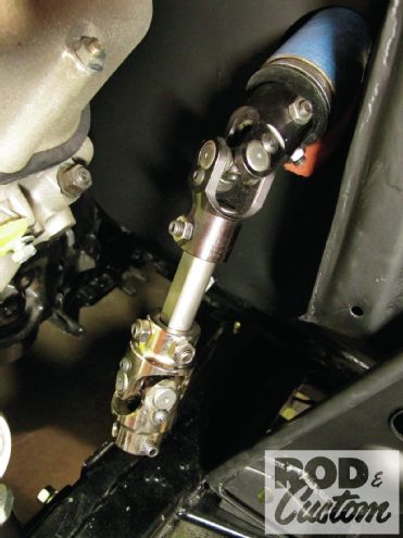
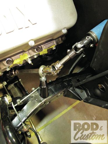 27. The finished steering installation. Remember, if you use three U/Js, you’ll need a support bearing on one of the shafts.